
Installation
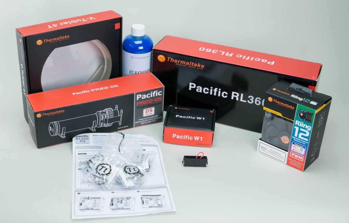
You’ve got all your parts out and sorted and now it’s time to get your loop built! First things first though, prep those parts. You will need to run either loop prep of some type or simple distilled water and cleaning vinegar through the radiator and CPU block to flush out any junk left over from the installation process. With that out of the way you can jump right into your installation!
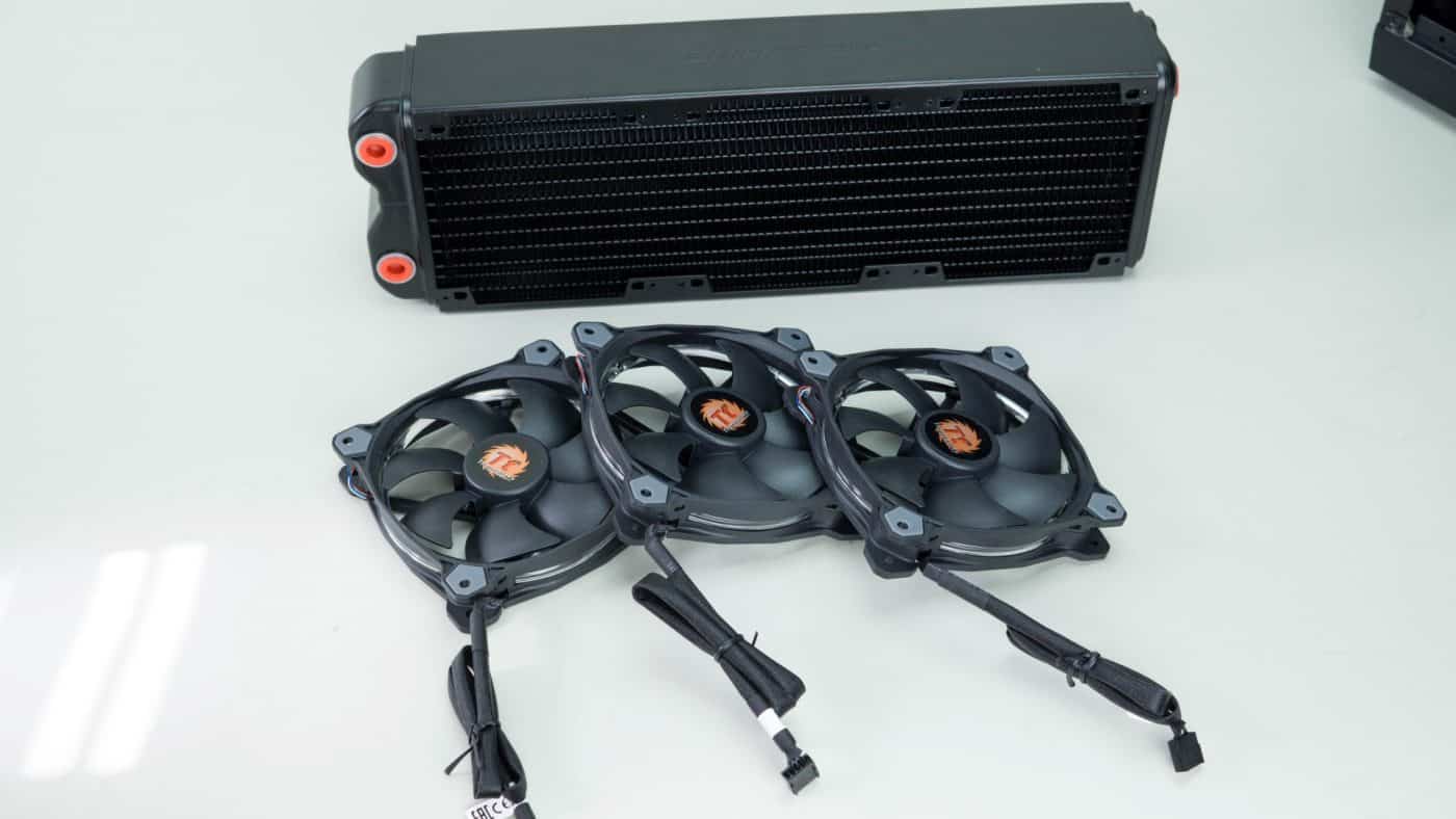
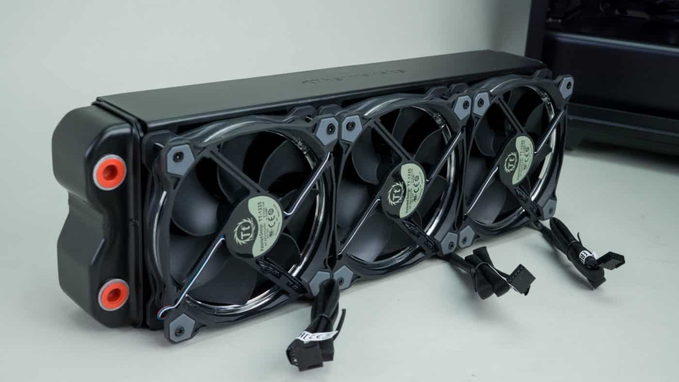
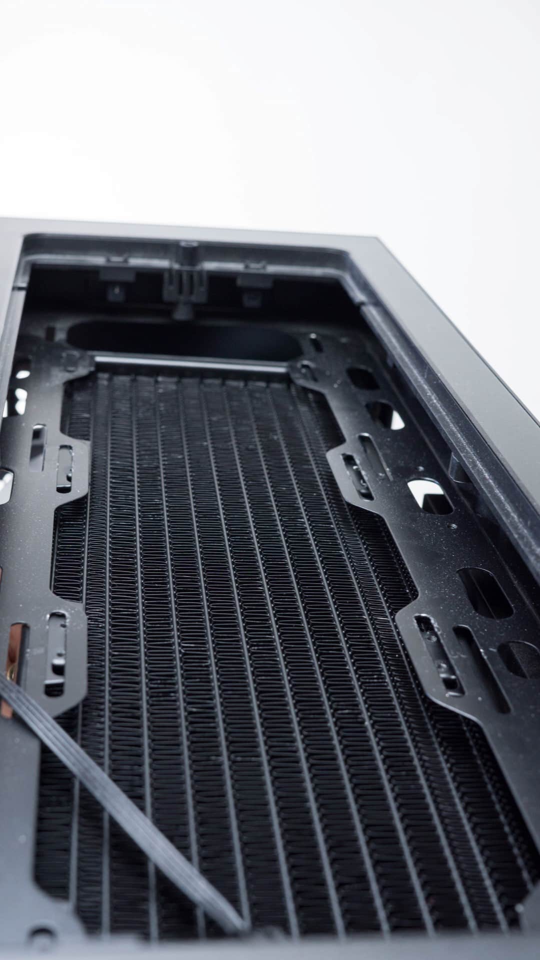
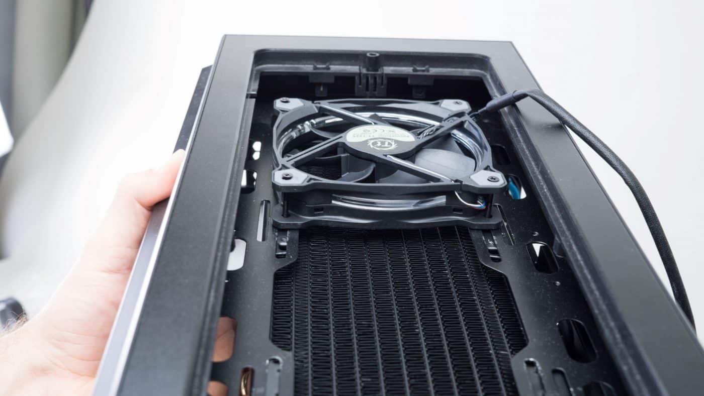
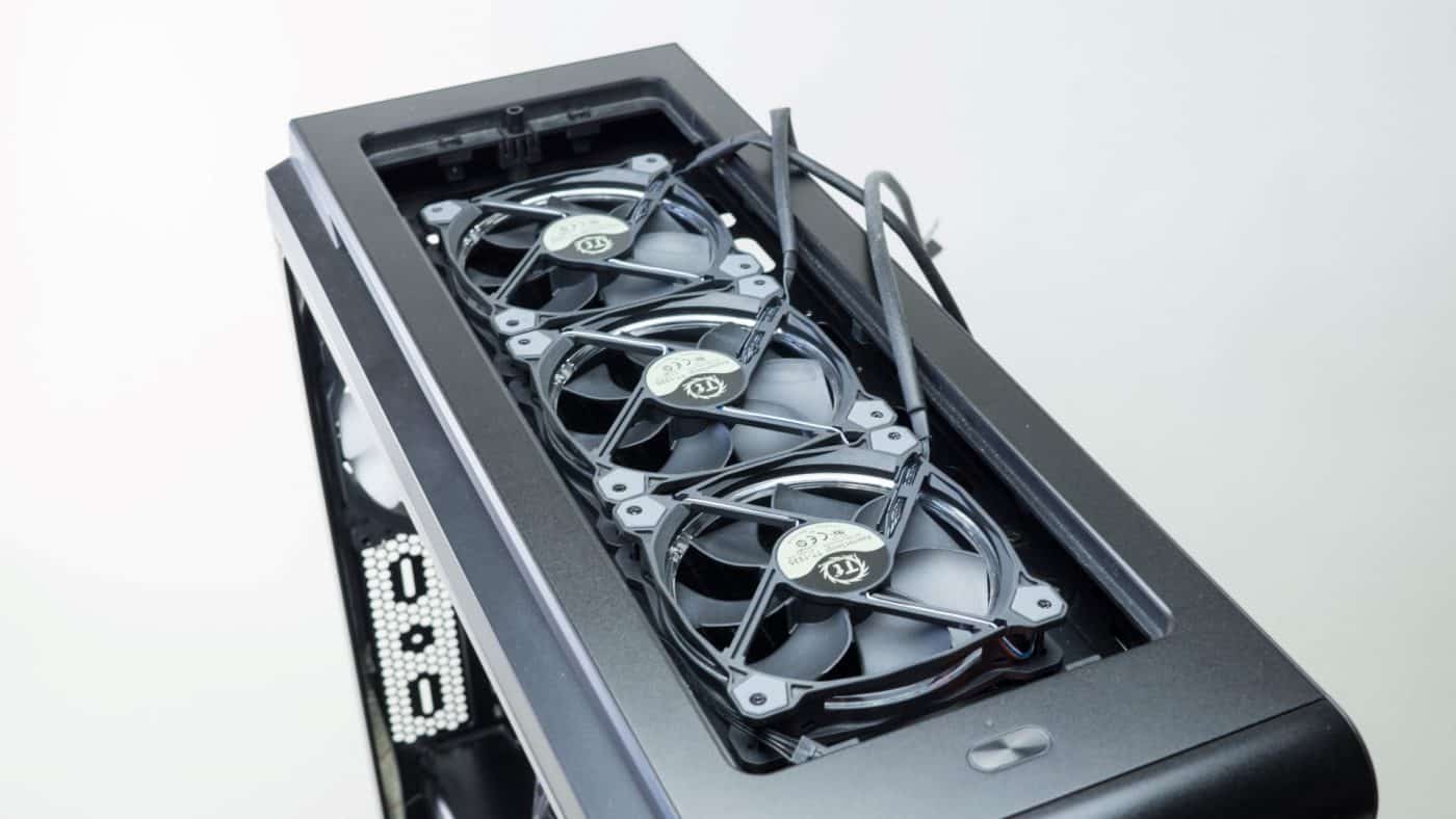
The first thing you want to do is test fit the radiator and make sure you will clear all the parts inside your case. Pay especially close attention to the installed ram modules and the heatsinks around the top of the socket. We decided to mount the radiator with the Riing fans attached to the bottom in pull configuration. Using either the screws included with the radiator or those included with the fans we attached them outside the case.
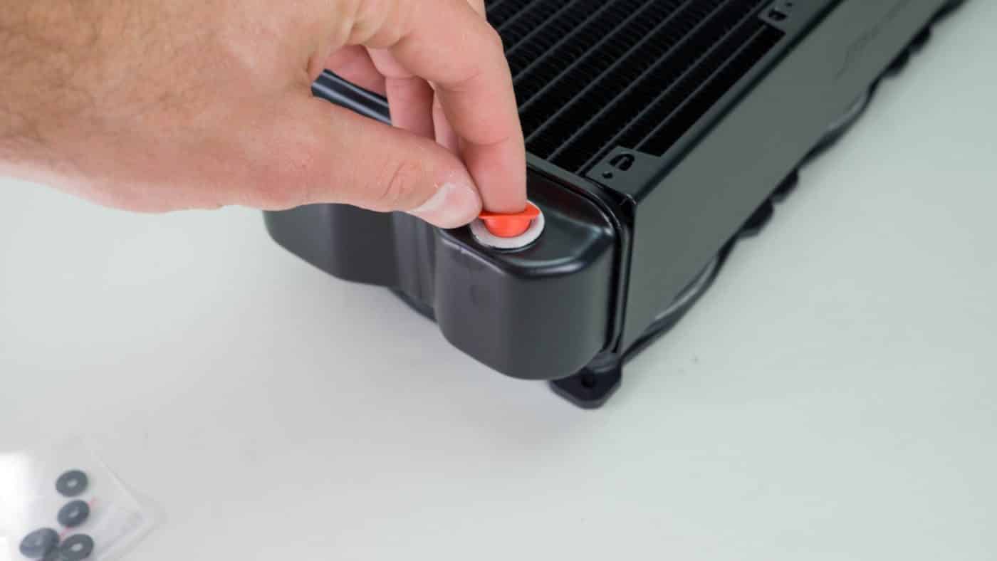
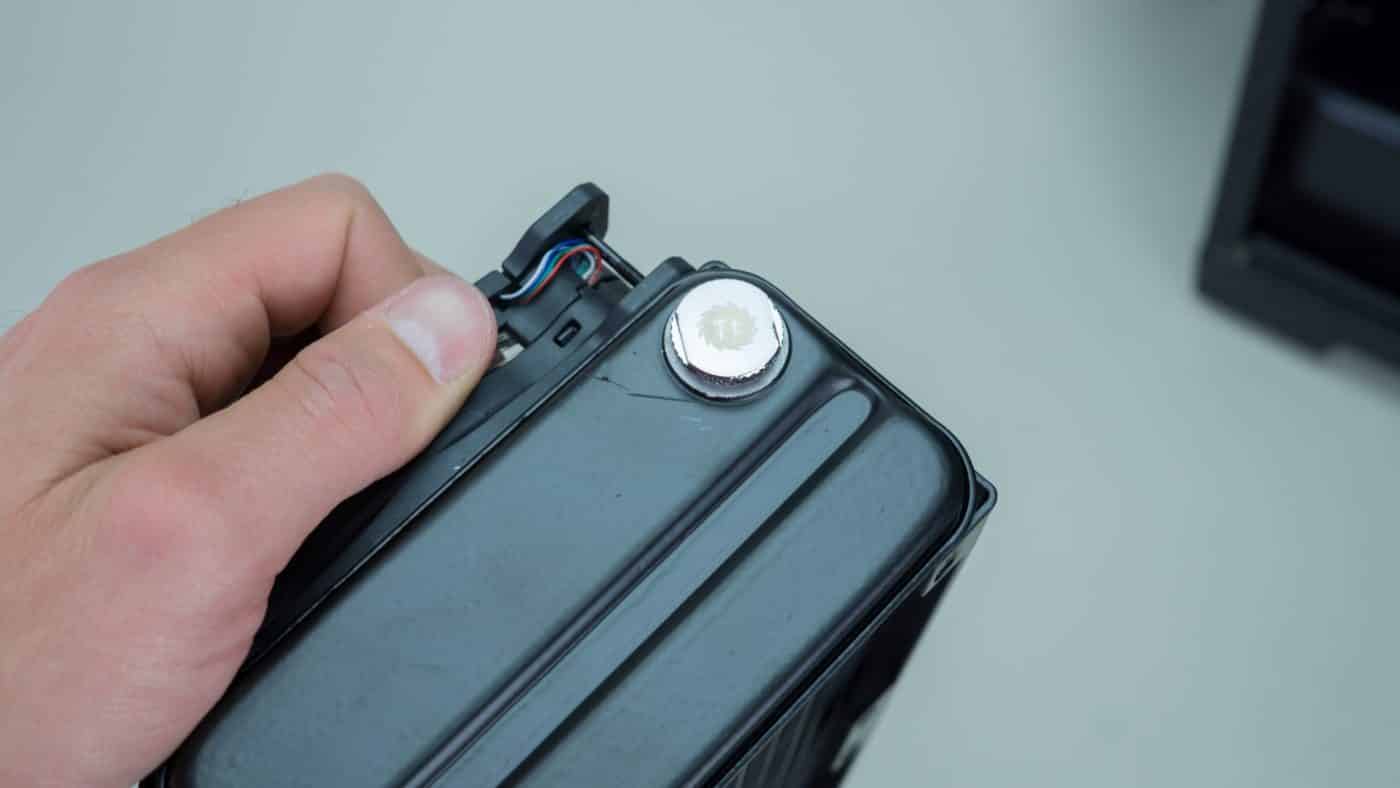
Next remove the red port plugs and install the three included chrome plugs into the extra ports on the radiator.

You can now install the radiator into the case. Unfortunately we ran into some problems at this point. While we did a test fit of the radiator we did not consider the extra depth of the fans. Unfortunately they run right into the heatsink around the socket and prevent the radiator from aligning properly in the top of the case.
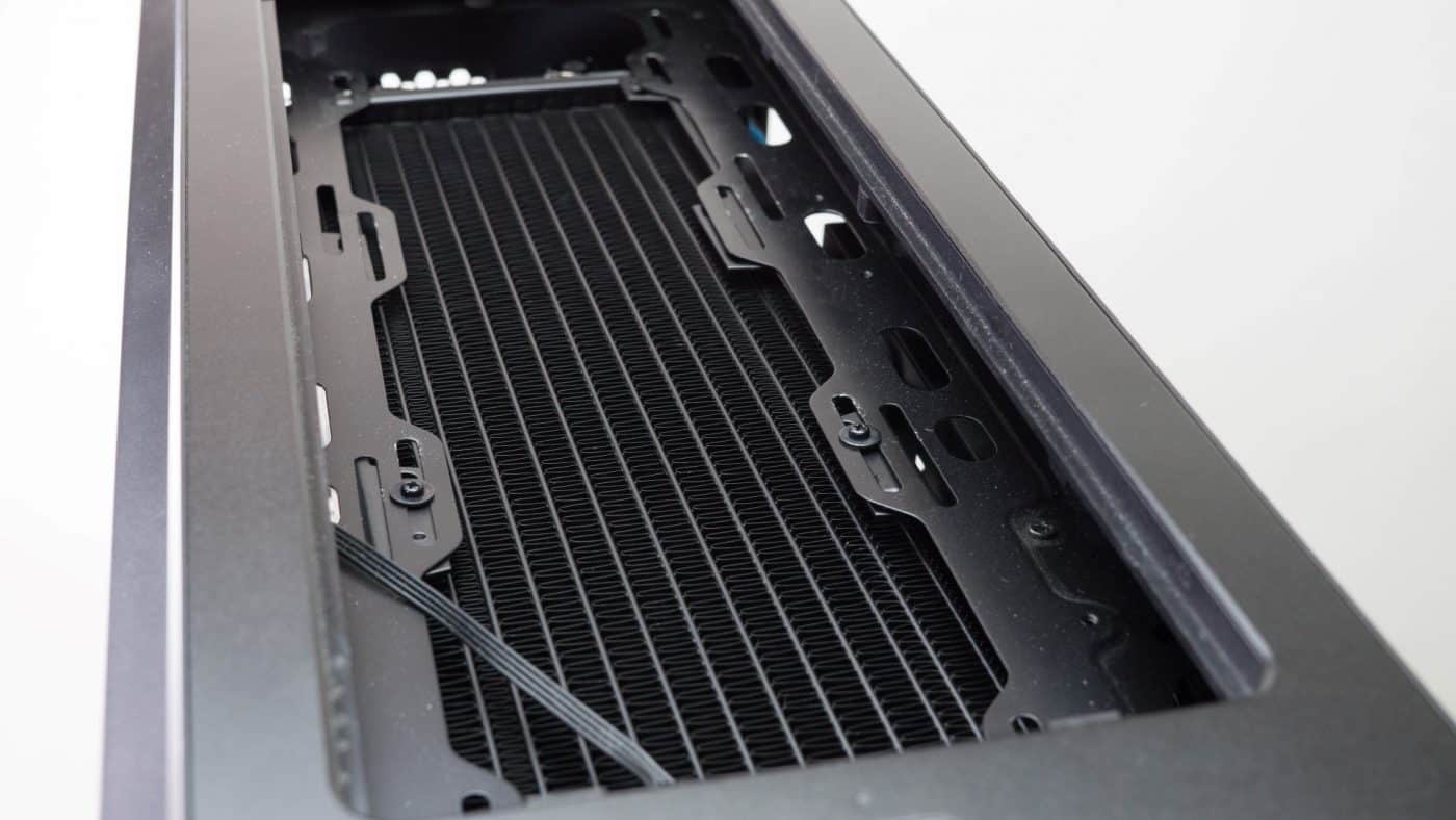
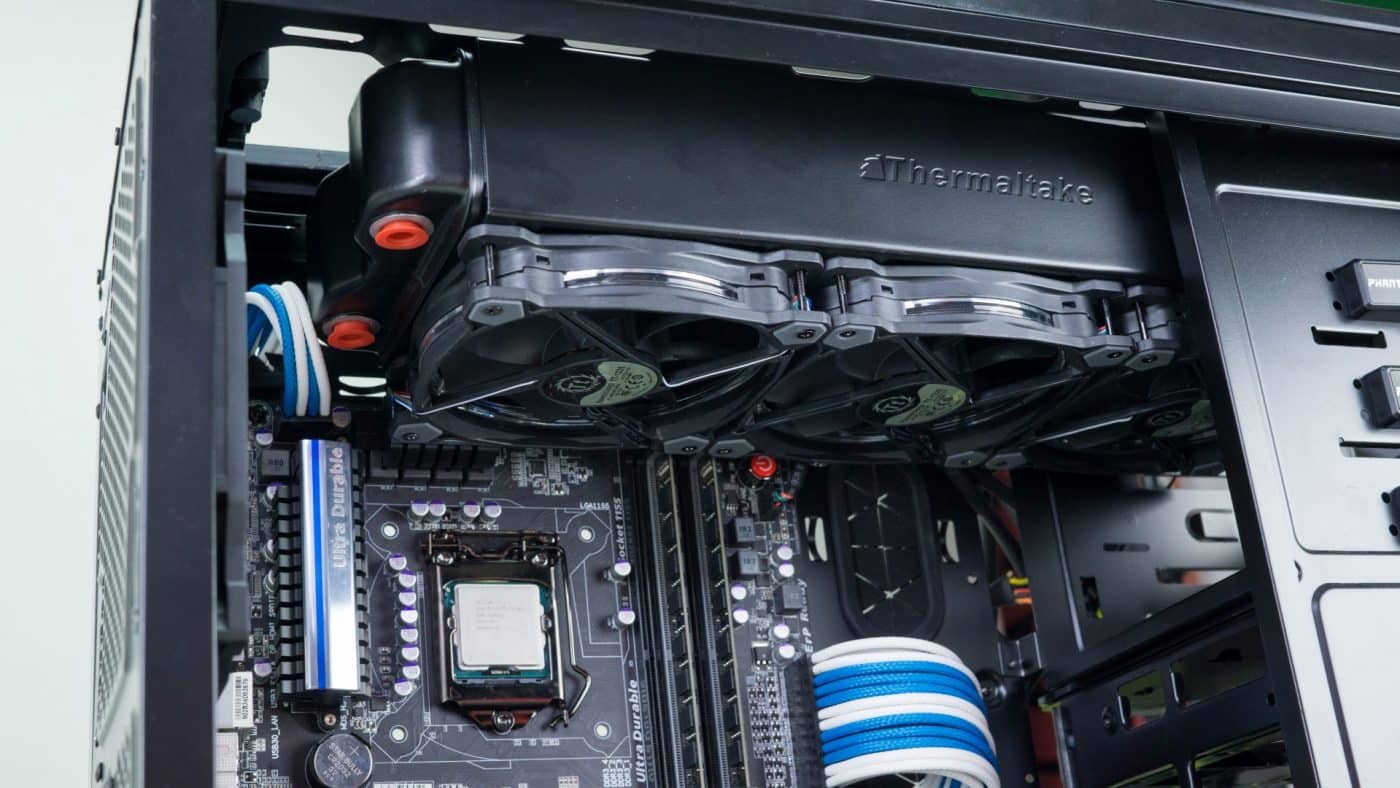
We could have left things this way and it would have been fine, but to do things properly we decided to remove the fans from the bottom of the rad and instead placed them so that the fan screws thread into the radiator and secure it in the top of the case.
This presents a really clean look, but we won’t get the illumination inside the case that the fans would have otherwise provided.


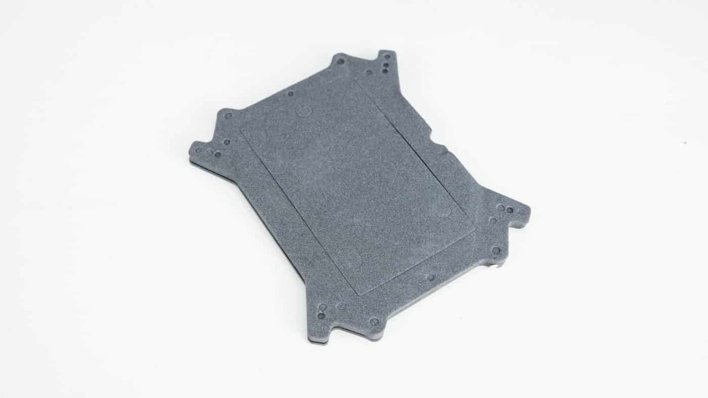
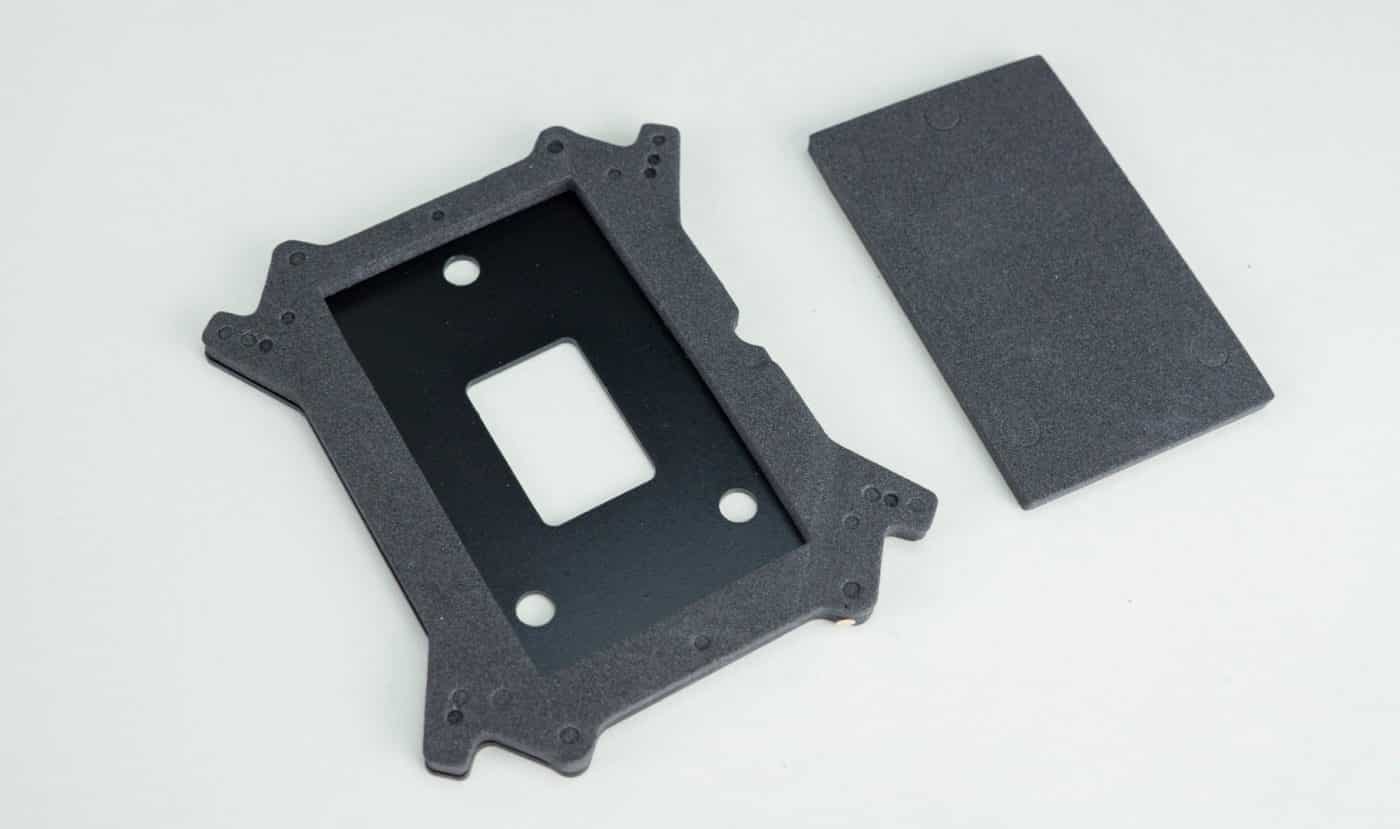
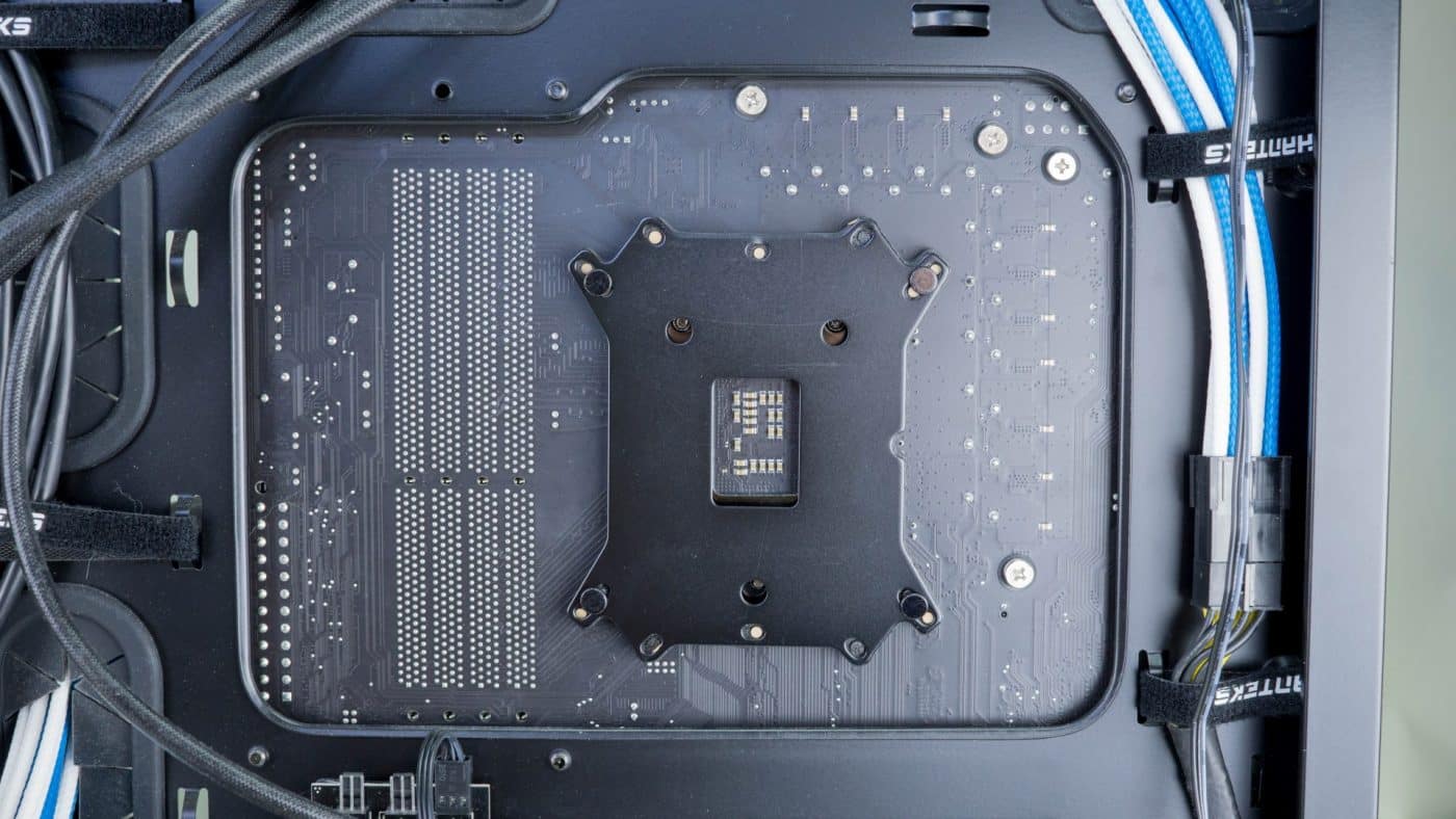
With the radiator all set in the top of the case we will now install the CPU block. Begin by prepping the backplate for your socket type. For Intel 115X remove the middle wedge of foam so that the interior space can be lined up with the back of the socket.
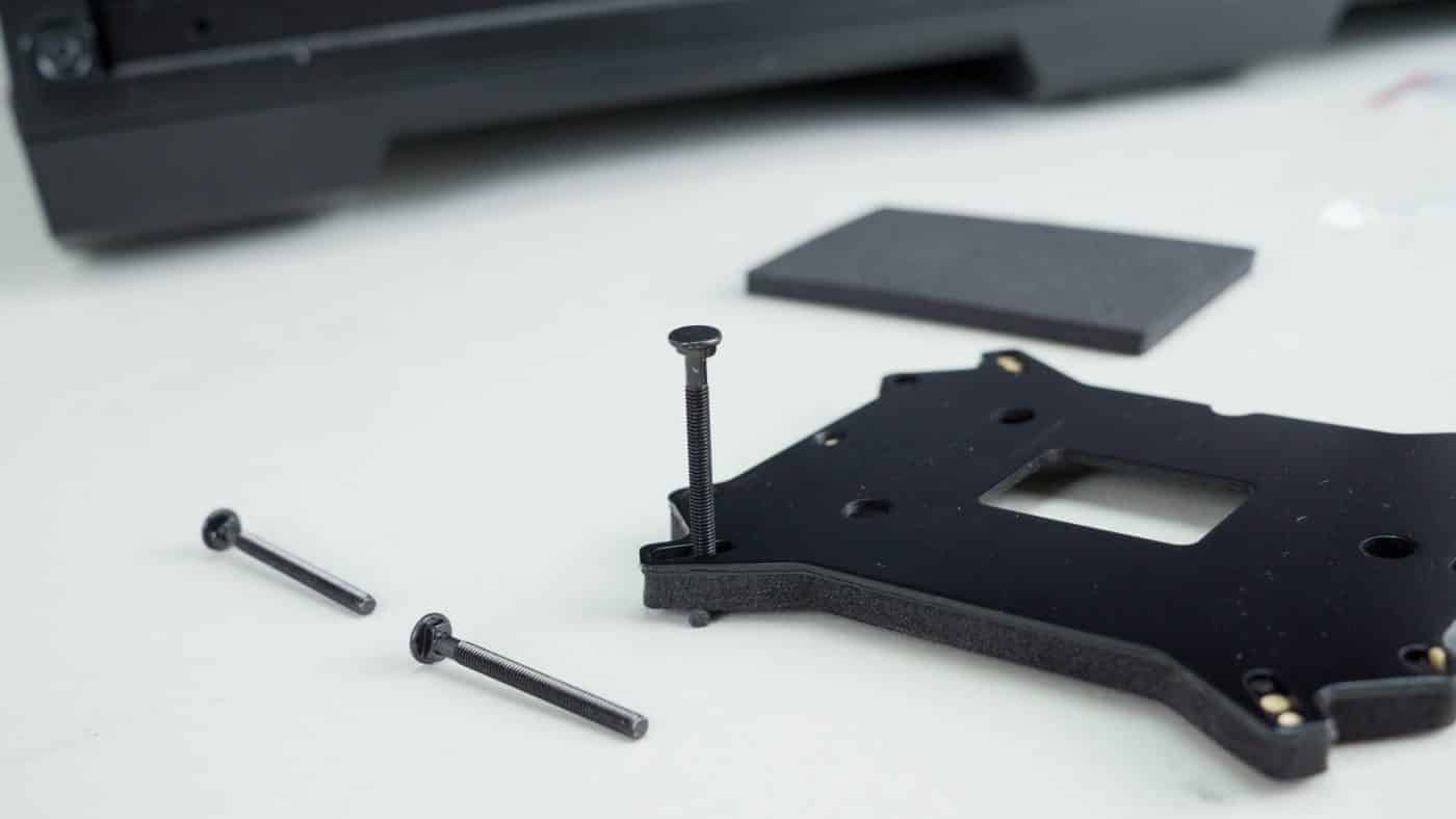
Now insert the stand off screws into the correct holes in the backplate.
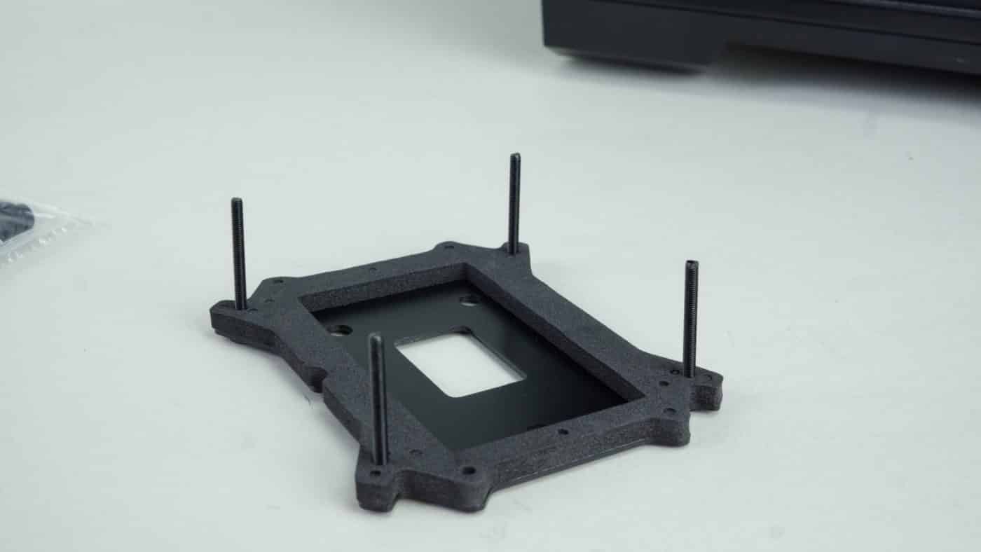
Finally align the screws with the pass through holes and insert them into the board. Going to the front of the board place one of the slightly oversized plastic washers on each screw. Now secure all four with one of the stand offs each.

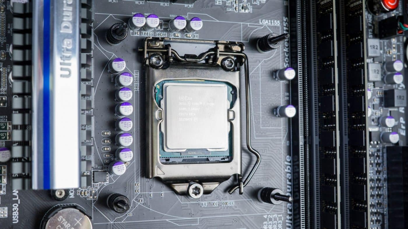
You’re ready to install the block now, but first you must apply thermal paste to the CPU heat spreader. The included X1 thermal paste is not very viscous, as such we recommend laying the case flat for the next couple steps or it might run down the bottom.

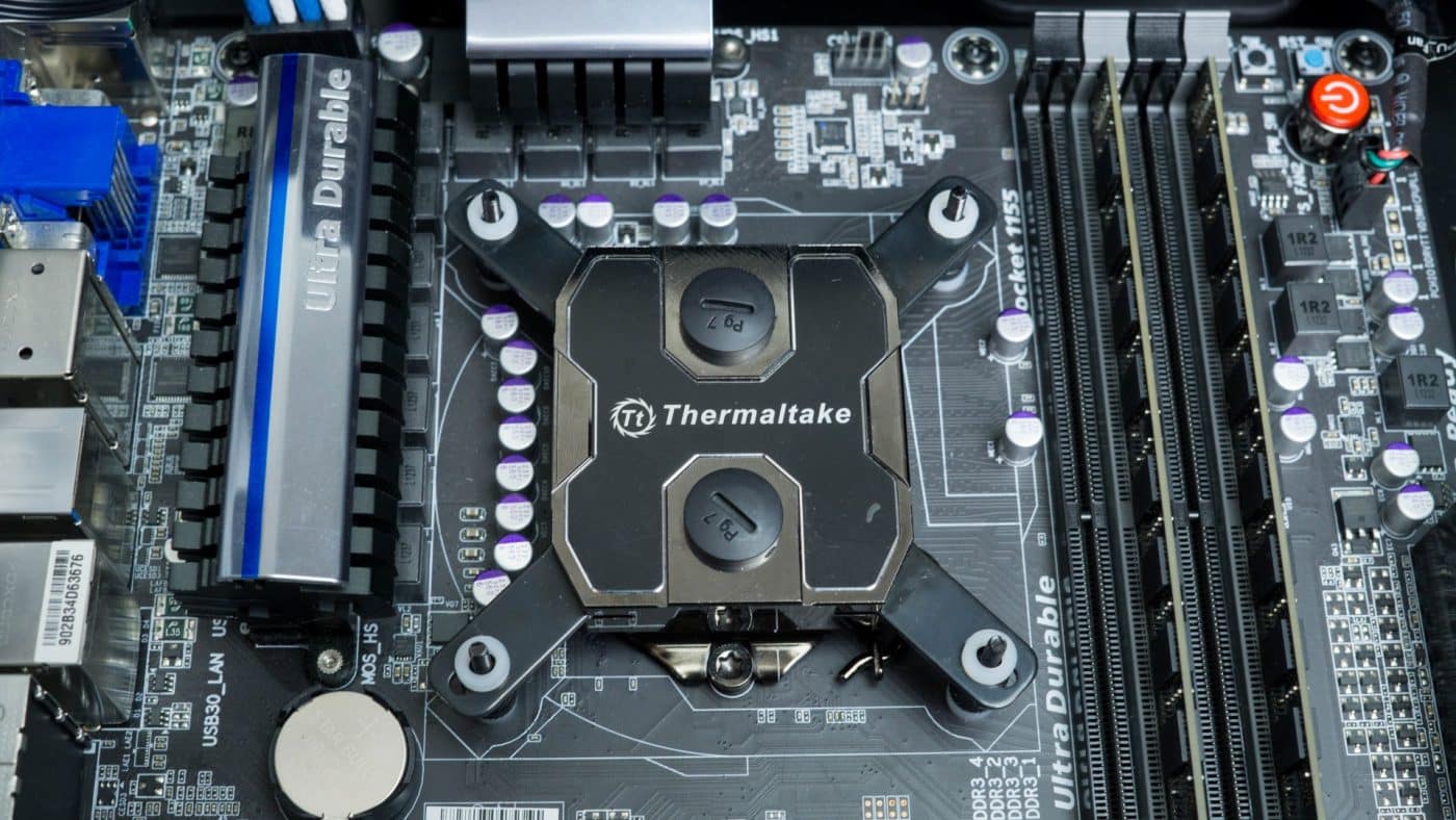
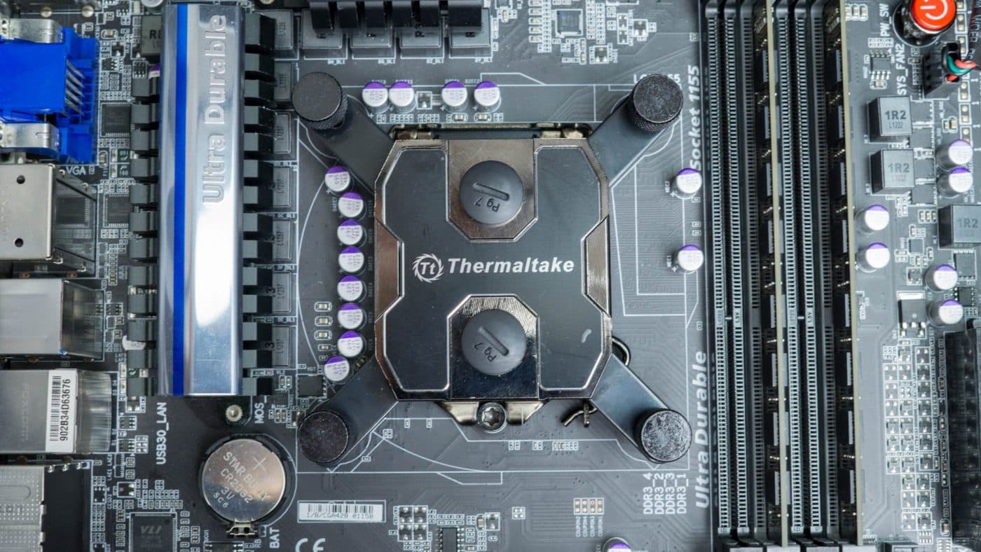
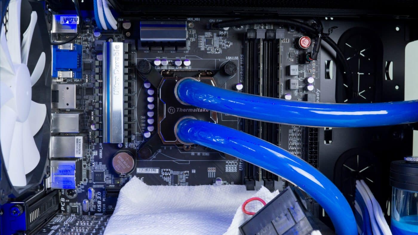
After removing the protective sticker from the base of the block align the mounts with the screws and press the block firmly on the CPU and hold it in place. With one hand holding the block in place, use the other to place four more washers, one on each stand off, and begin securing the block with the thumbscrews. Alternating along the diagonals, these should become fully finger tight.
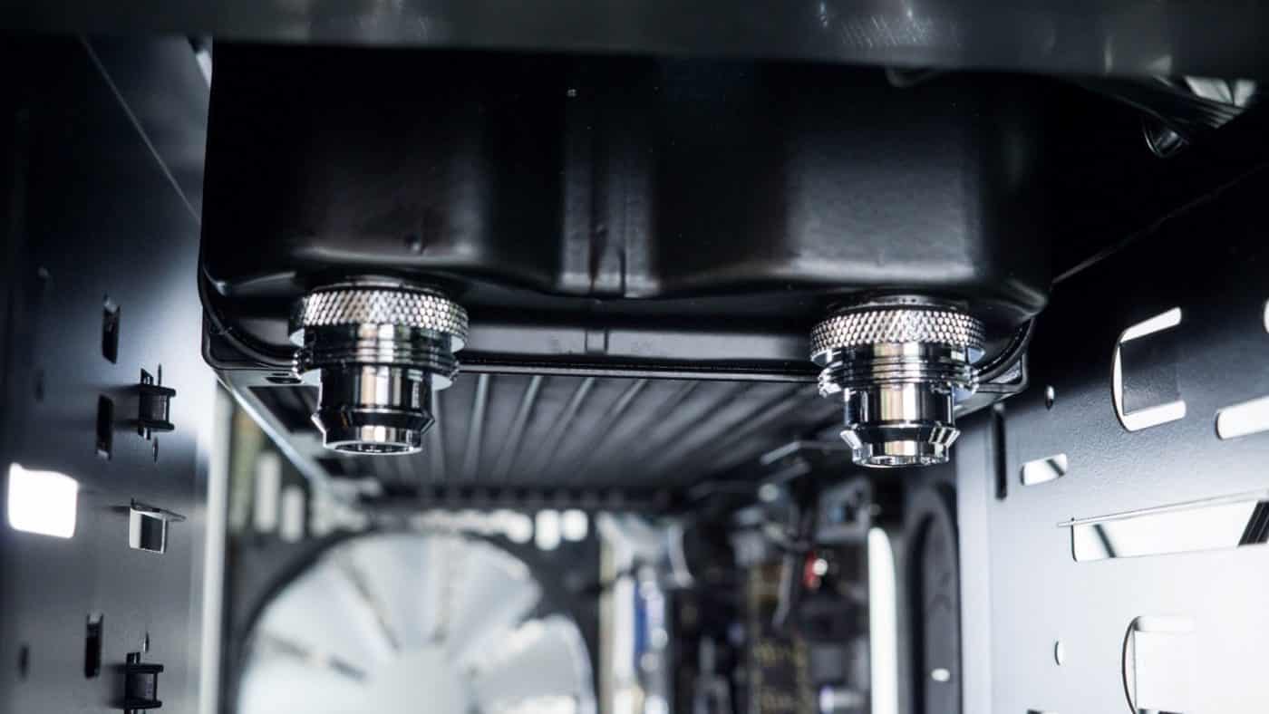
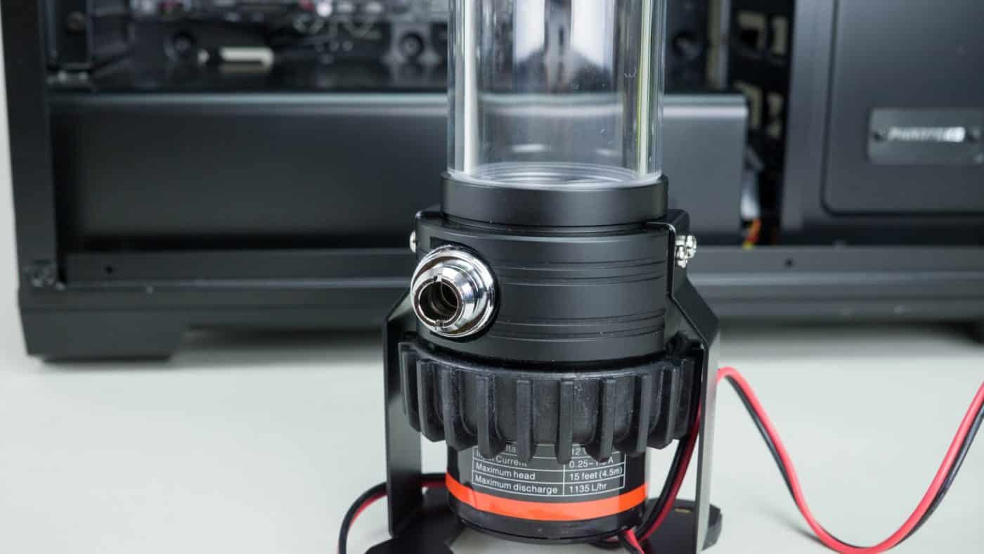
Now would be a good time to install the compression fittings. Two on the CPU, two on the radiator, and the last two on the pump/reservoir.

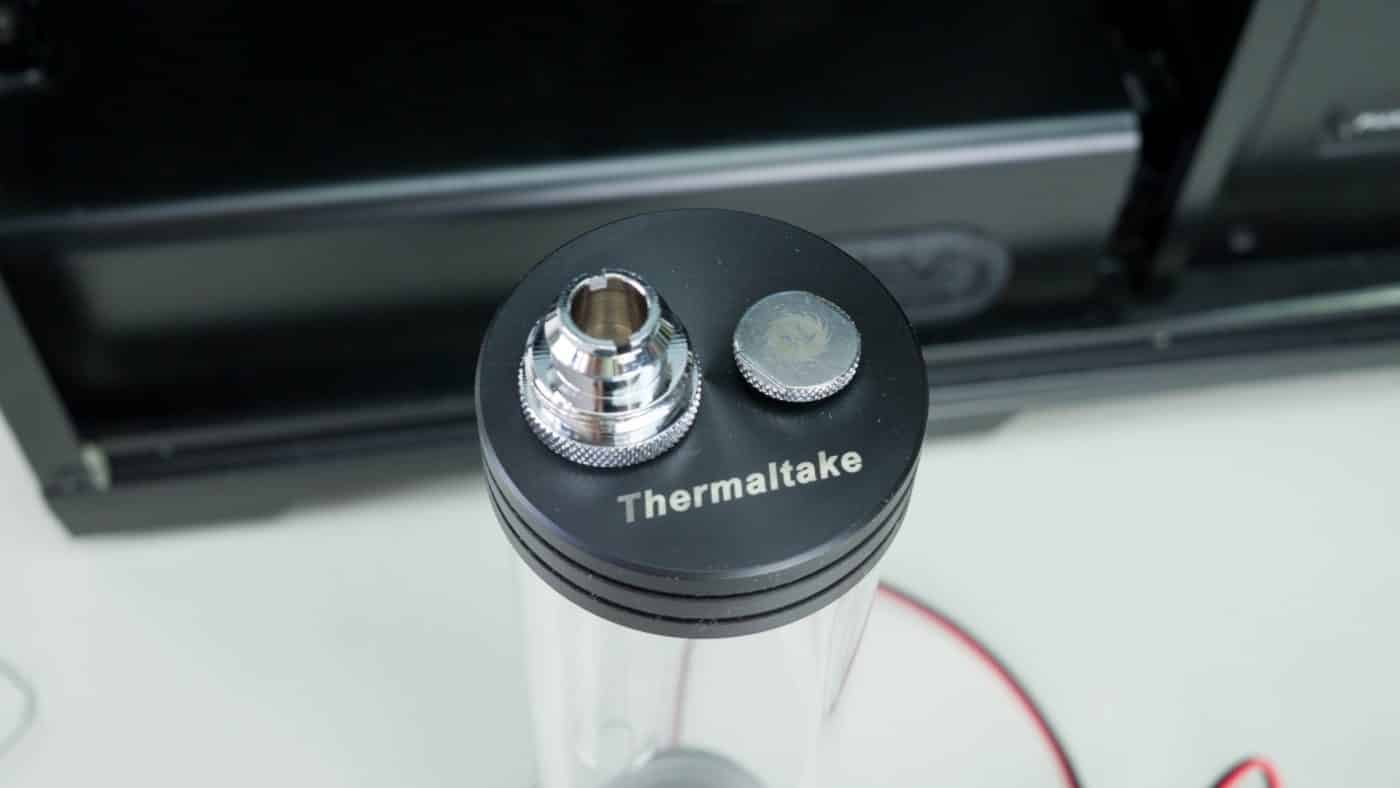
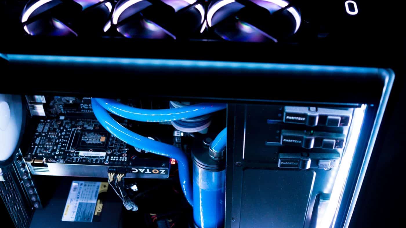
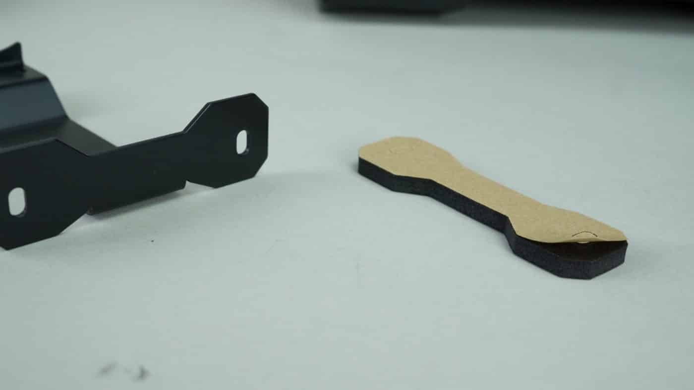
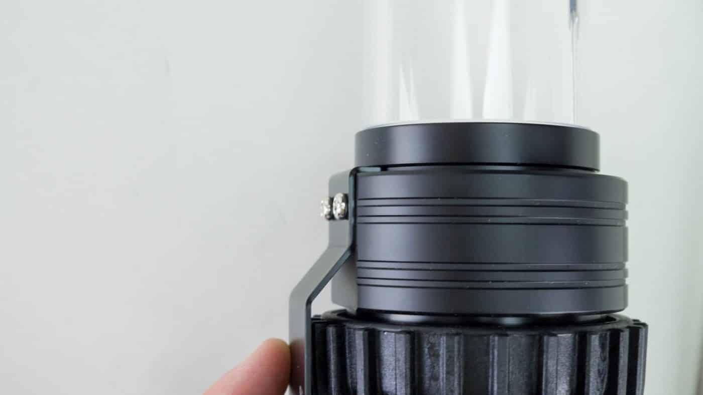
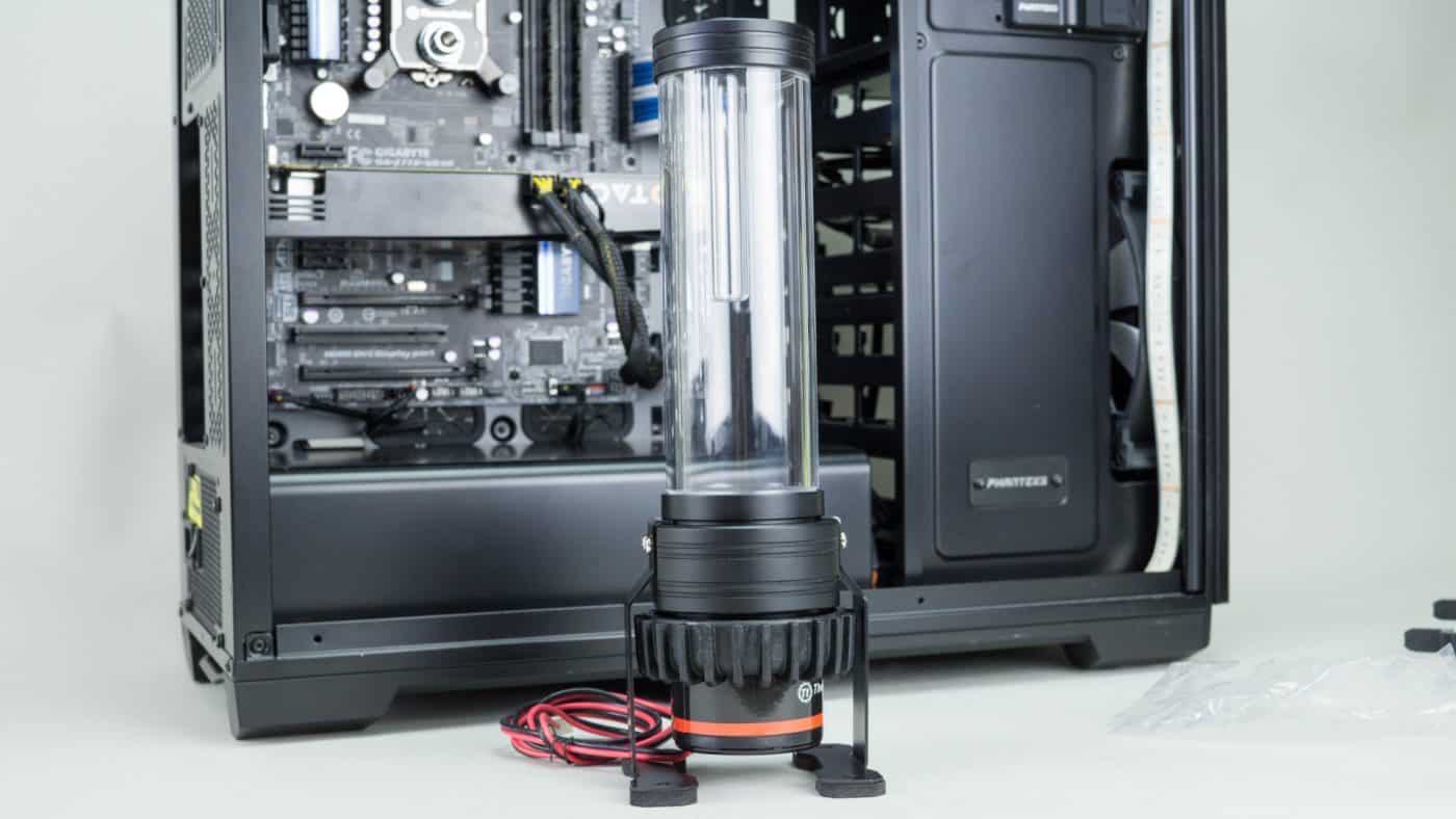
Our last component left to install is the of course the PR22-D5 combo. While you can install the unit with the mounting rings on the interior wall of your chassis, we opted to go with the included legs instead. Without modding our test case, the PR22-D5 is just too tall for the ring mounts. Before we attached the legs to the pump housing we apply some anti vibration pads to be base.
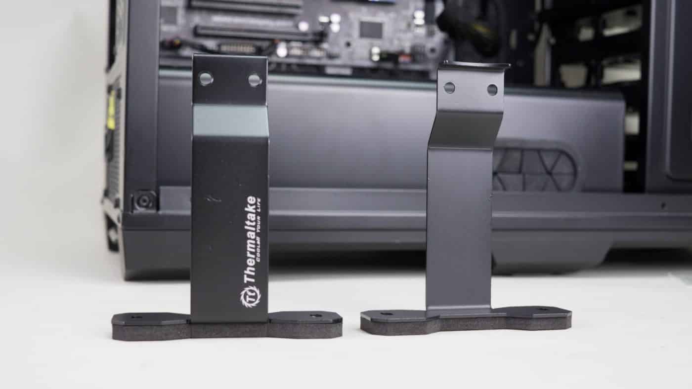
Now simply line up the holes on the legs with the holes on the mount and secure with the included screws. Repeat for both sides and you are all set to go!

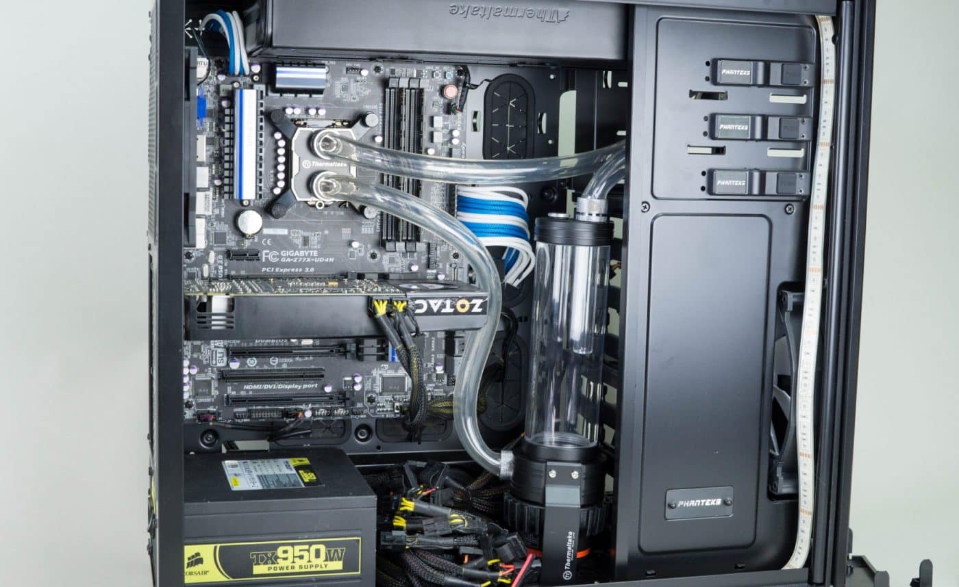
We had a general idea of where we want the pump and res to go, but after a test fit we find that once again the unit is too tall for the open space in our mid tower test rig case.
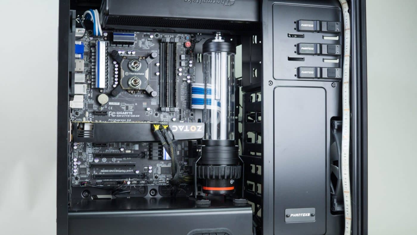

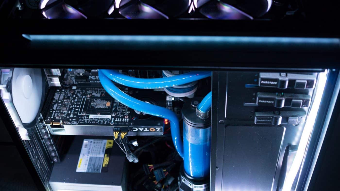
As a result was have to abandon the PSU shroud and place the feet on the floor of the case. The only real downside is that we now have an ugly pile of wires exposed.
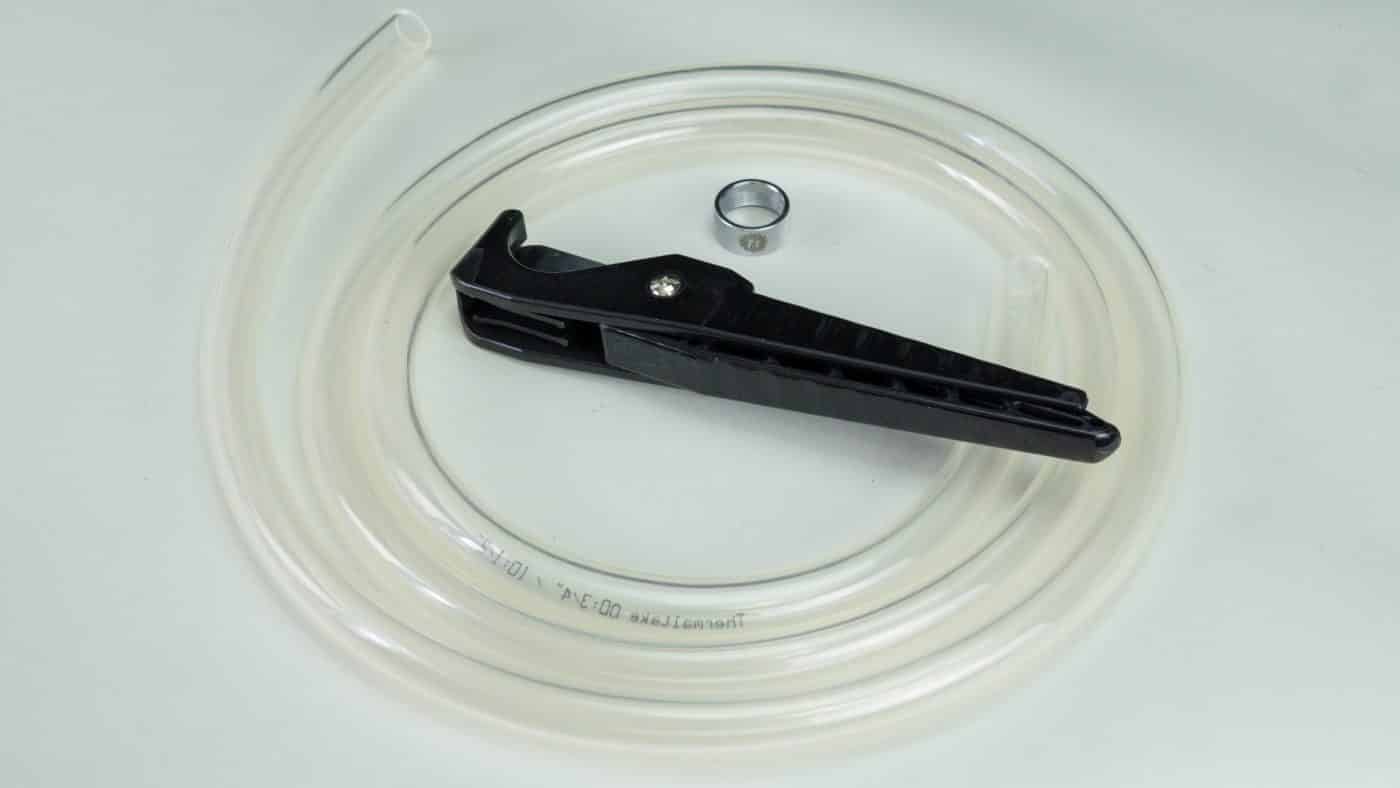
Pressing on it’s time to start installing tubing! We have a fancy tubing scissor tool, but you can get by with regular craft scissors or a knife if you have to. Begin by placing a locking ring on the tubing and attaching that end of the tubing to your starting fitting.

Secure that fitting and run the tubing to the next connection you plan to make. Give yourself a couple extra inches and cut it off. Place another locking ring on the tubing, attach it to the fitting, finally secure it with the ring.
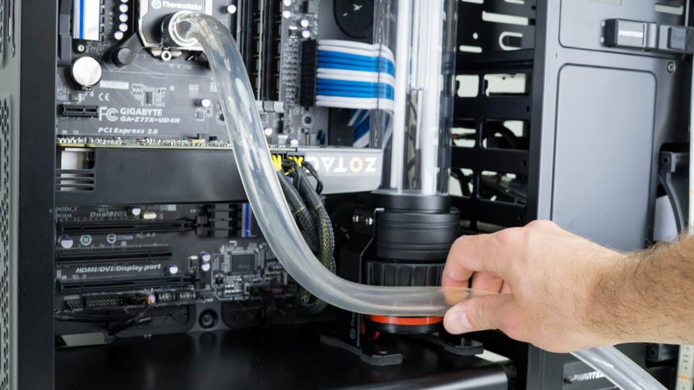

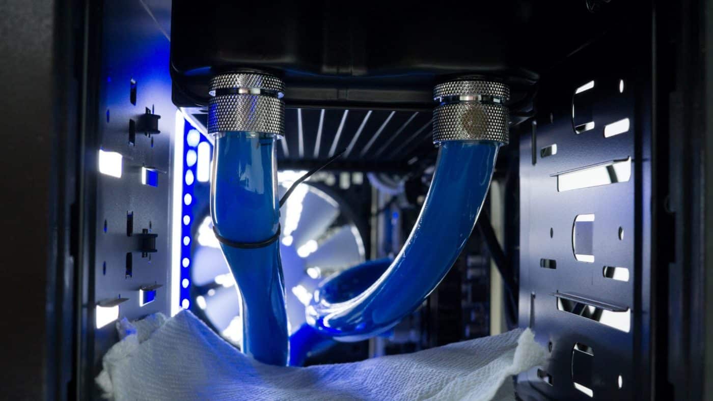
Repeat the same process for the other two pieces of tubing. Do your best to avoid a kink like the one pictured. It’s caused by forcing the tubing to bend at too hard of an angle. If it is unavoidable you can attempt to correct it with the addition of anti-kink coils or some cleverly placed zip ties.


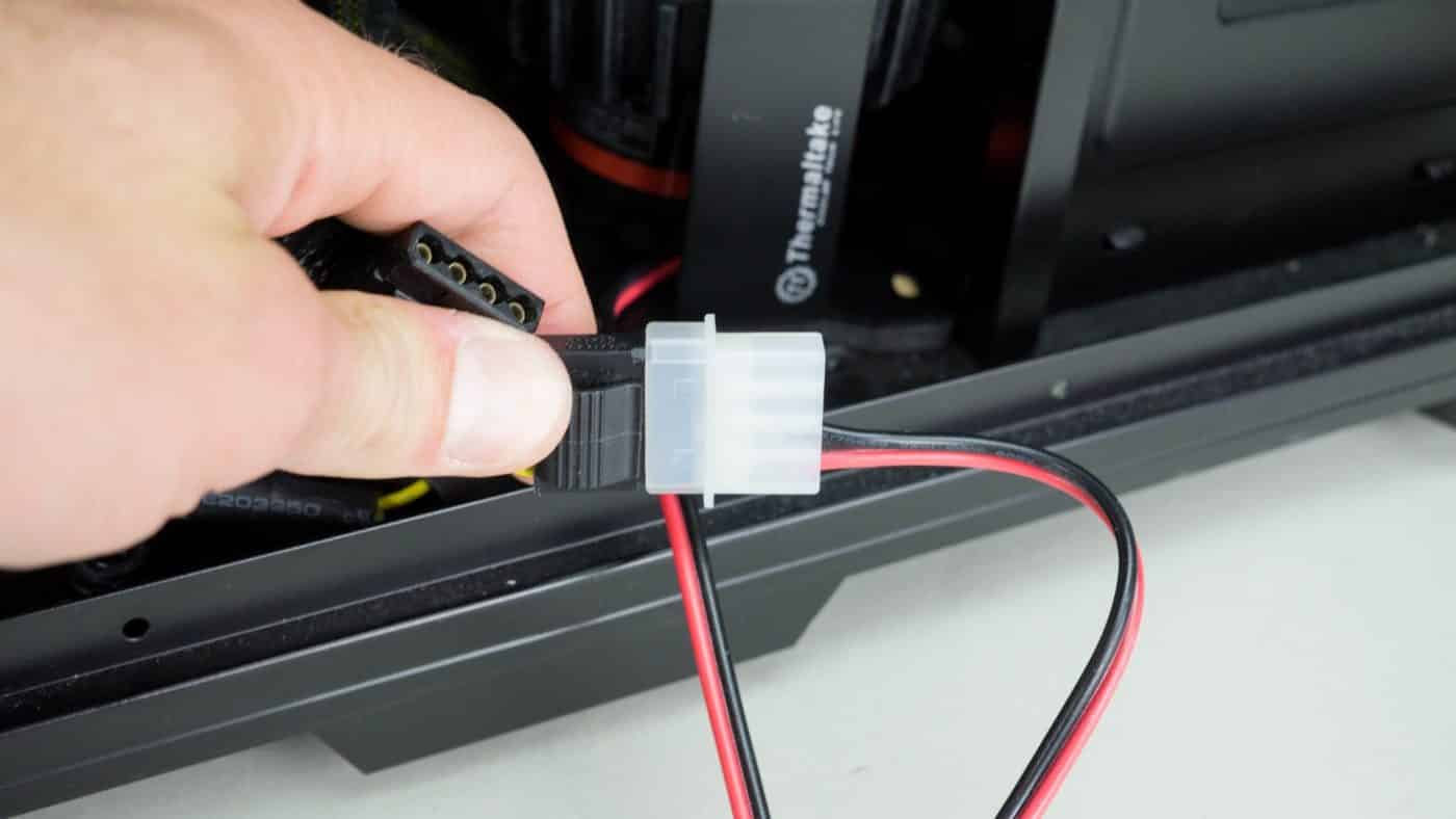
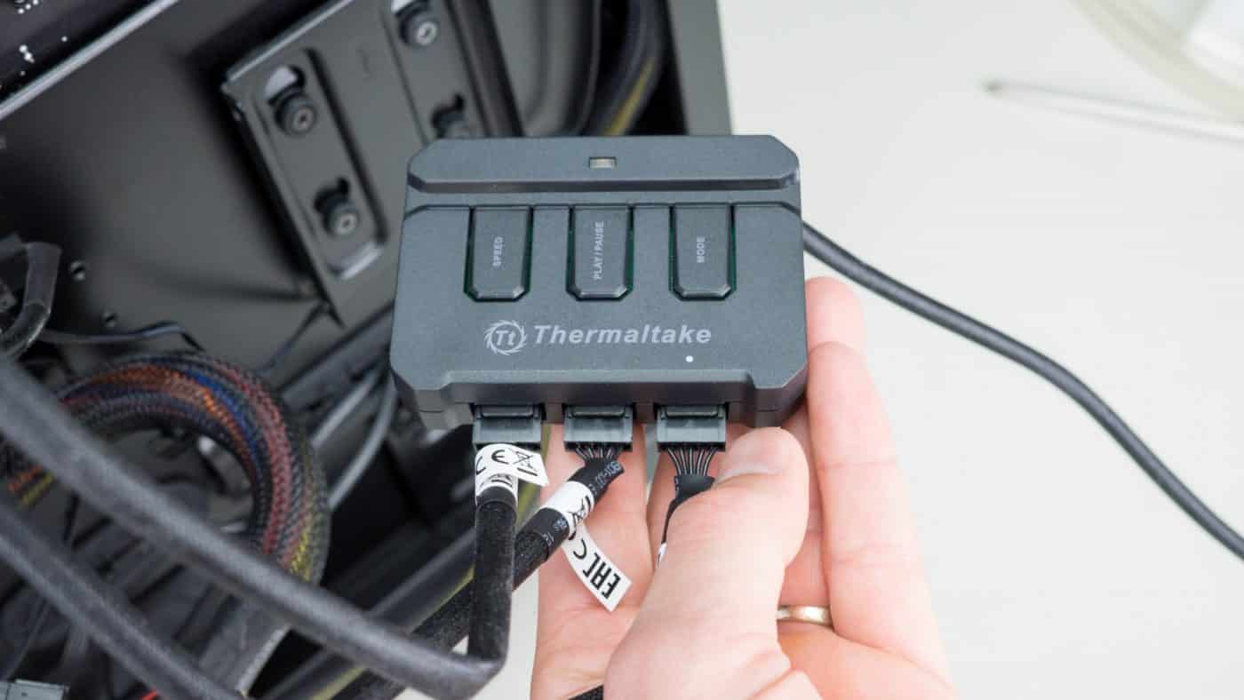
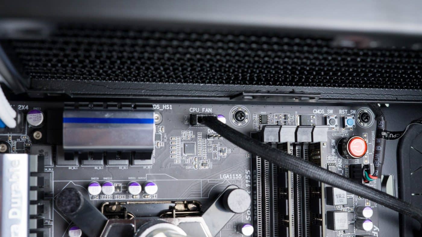
Pat yourself on the back, the water cooling gear is now installed and ready to go. We must now make the few necessary electrical connections. First attach the female molex connector from the pump to an open connector from the PSU. Then be sure to connect the three fans to the controller and that to the CPU_FAN header on your motherboard.
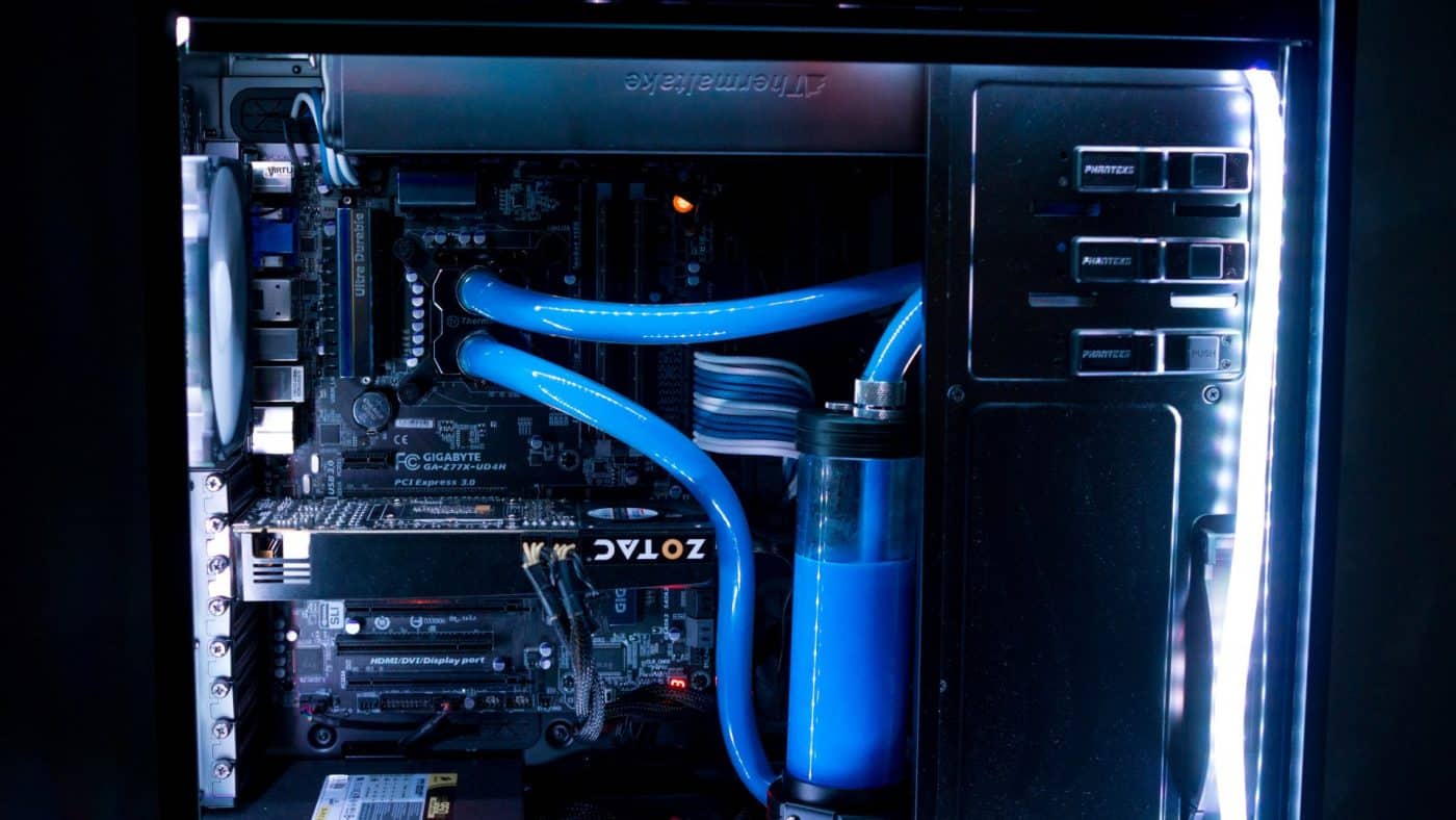
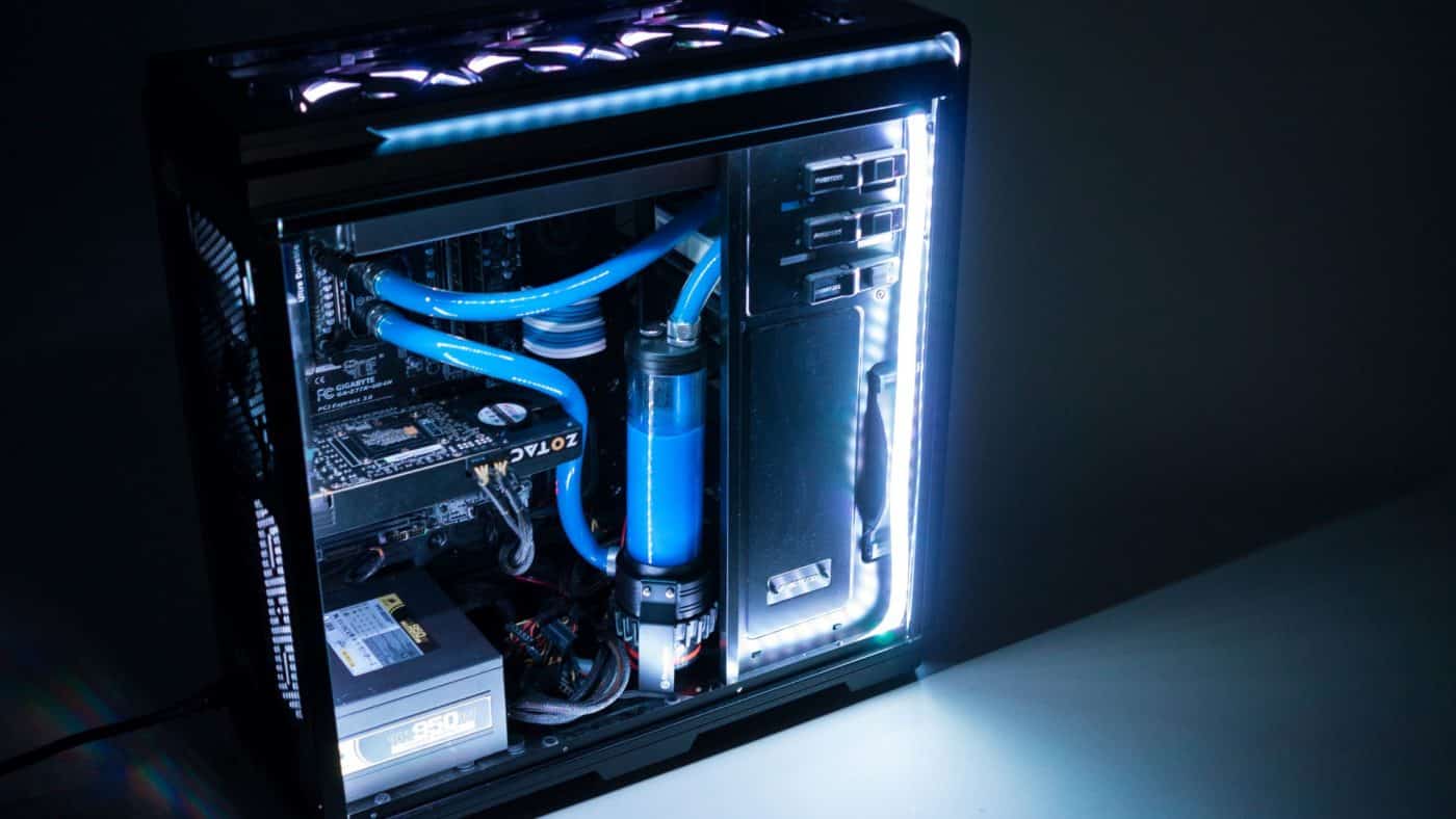
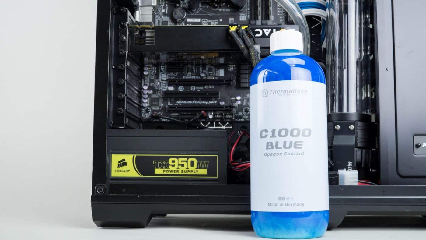
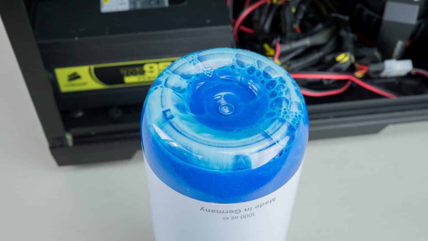
Now for the fun bit, filling the loop! We will be adding the C1000 Blue coolant to the reservoir, but before we got into it we shook the coolant up a some as there seems to be a bit of settling in the bottle.
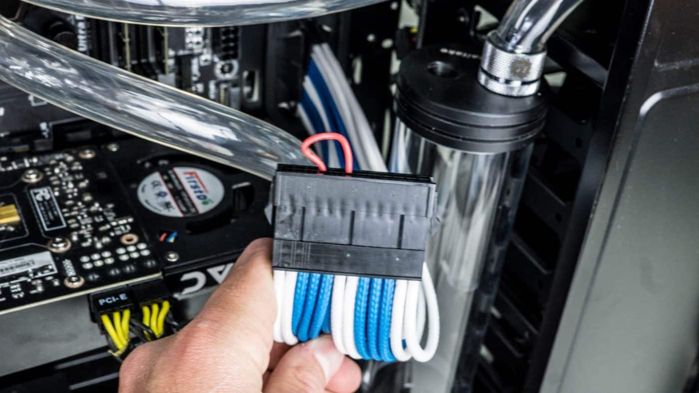
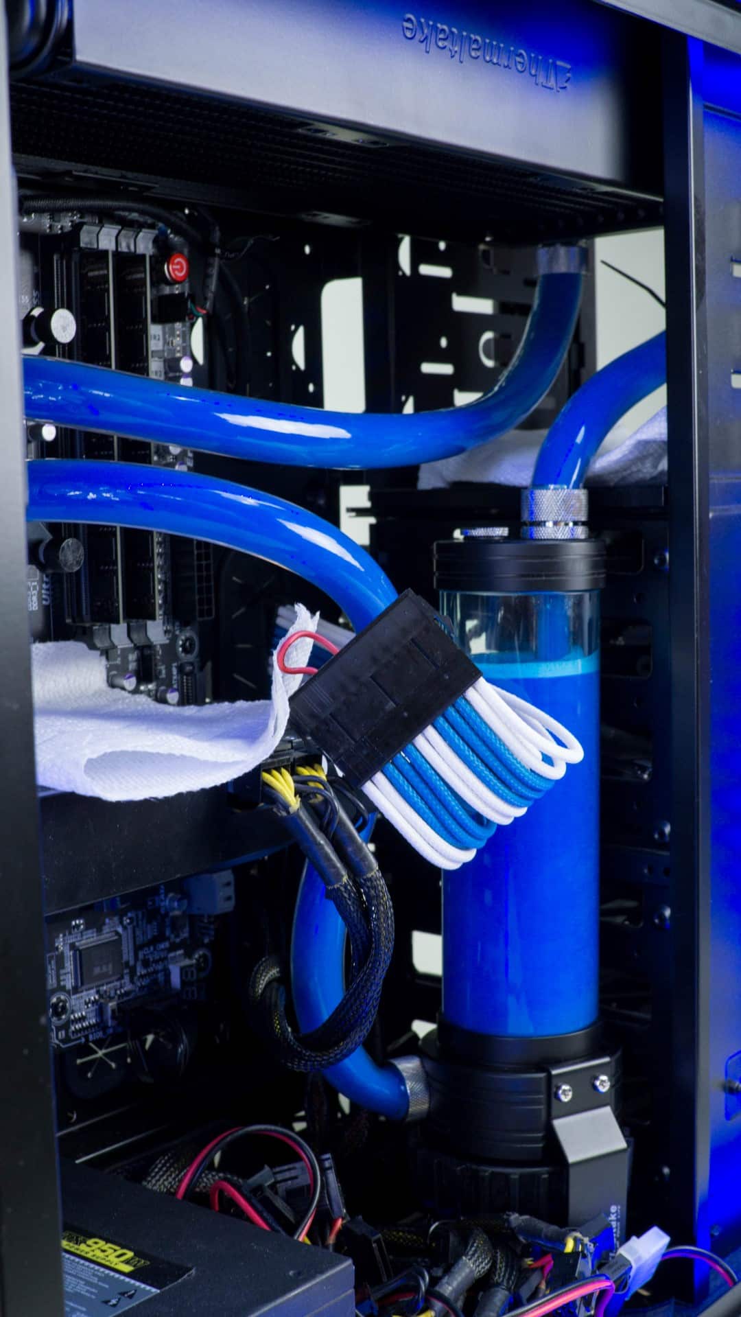
As a safety precaution place paper towel under the three locations where you have tubing connecting to fittings. The paper towel will not only work to absorb any leaks, but will also show a leak is happening very quickly and obviously. Remove the plug from the open port and insert your fill tube. Plug the 24-pin jumper into the 24-pin cable from your PSU.

Fill the reservoir until full, switch on the PSU letting the pump draw the coolant into the loop. When it gets near to the bottom of the reservoir switch the PSU off and refill with coolant. Repeat this process until the loop is full and there is coolant running freely and easily through the entire loop.

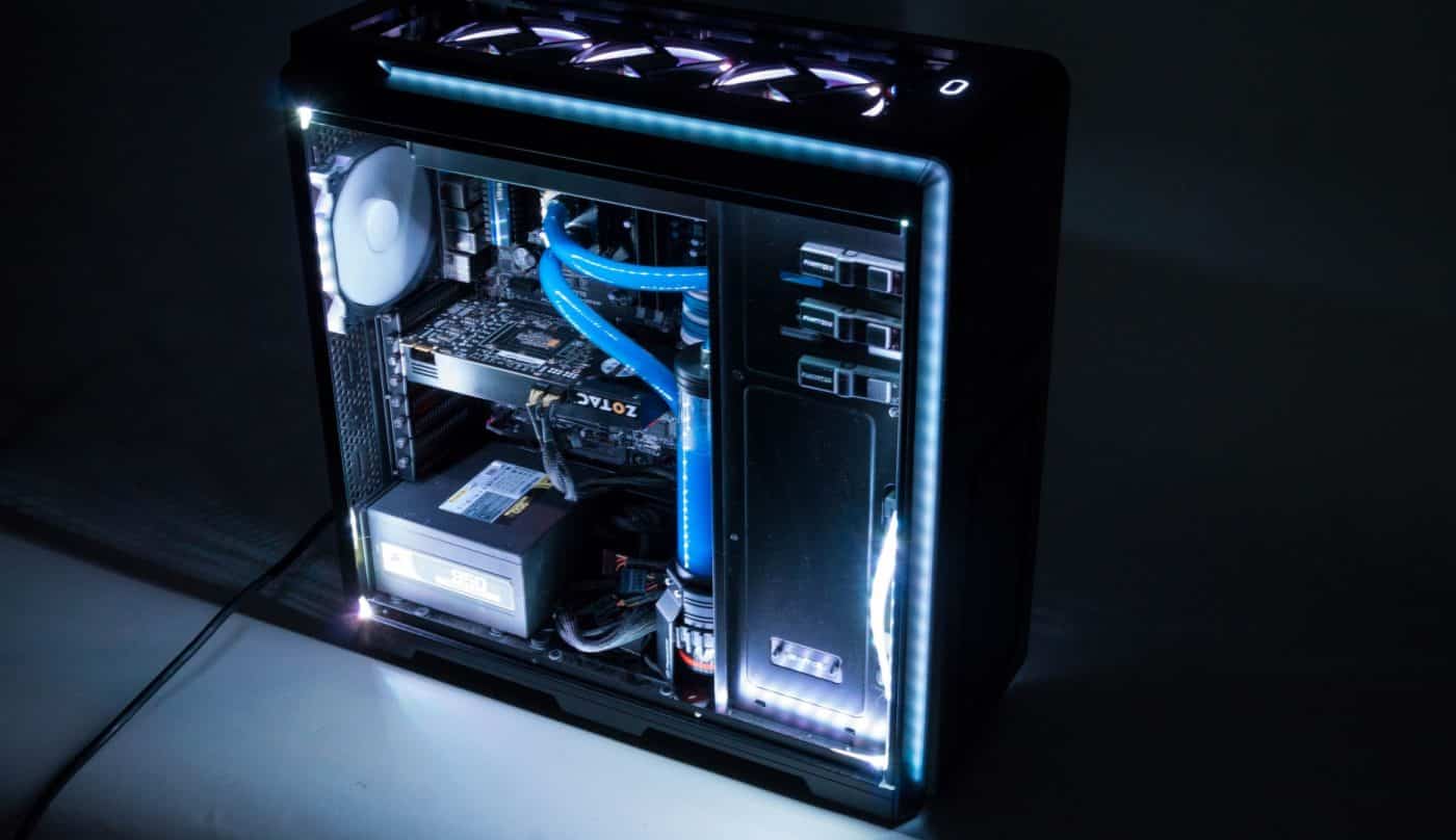
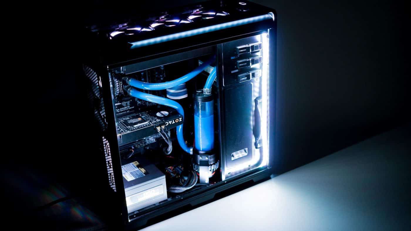
At this point you are done! Let the loop run as is for no less than 12 hours to ensure no leaks develop. After this period turn the psu off and plug the 24-pin cable back into the motherboard. You are now ready to power your rig up and find out what effect your hard work has had for your CPU temps!