
Building in the Silverstone Fortress FT04
Since I did not do a Triple radiator cooler install in here I did want to show a drawn representation of how a large 360mm x 120mm Radiator will look if you decide to go with a water cooling solution. Mainly you need to use the black brackets to change the 180mm vent holes down to 120mm. This configuration stretches the tubing unless you are doing a custom loop design where you can place the pump at the top of the case. This case allows for this type of cooling solution but with all in one coolers being so popular this is probably another reason why people didn’t get as excited about this case. This case was primarily built for air cooling and its more optimized for that sort of cooling solution.

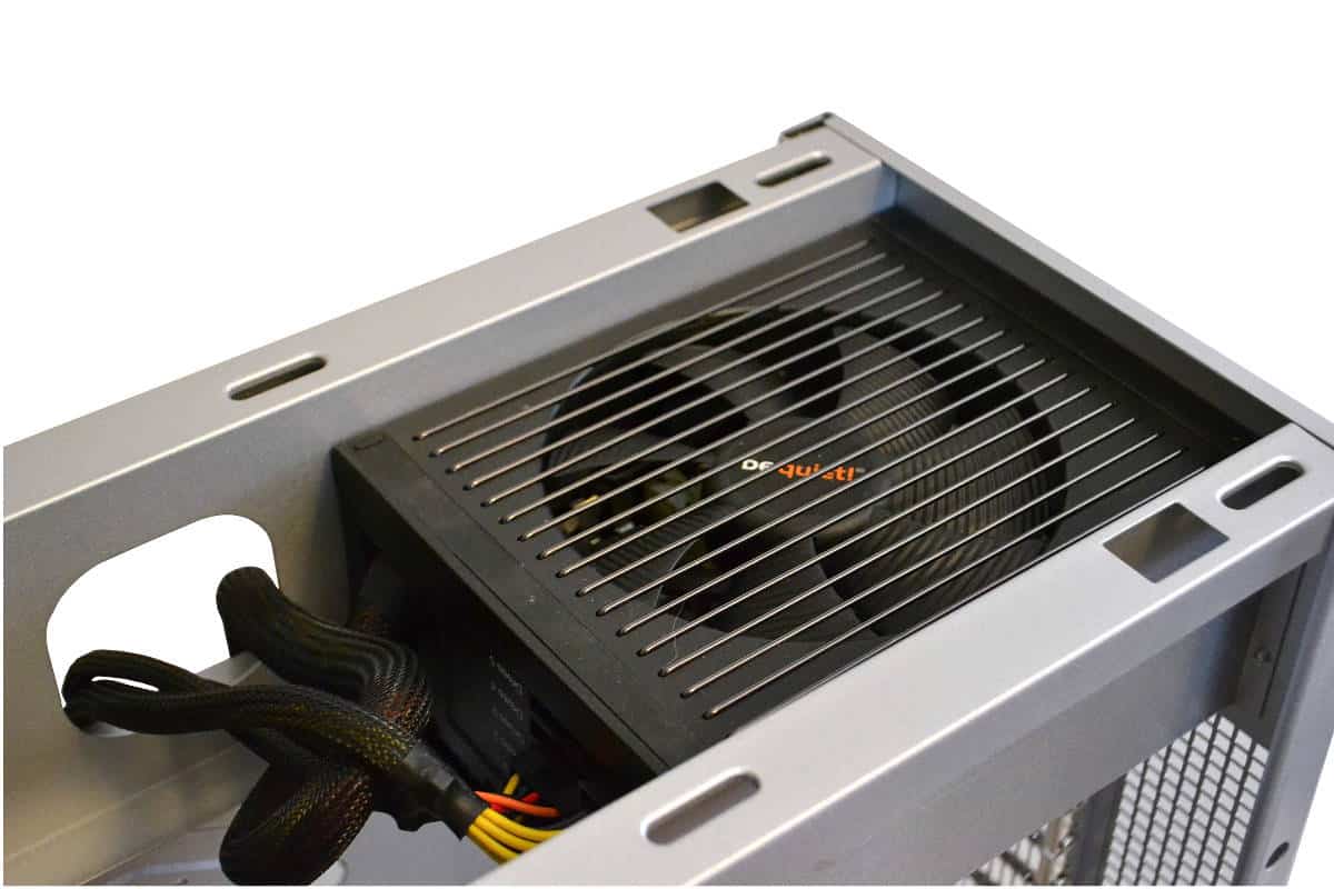
Setting the Power Supply in the top mounting point is so easy that showing it is just entertainment. It fits perfectly for fan up or fan down configuration and it works well this way since the motherboard is reversed. The rails on the bottom are rubber coated to eliminate as much vibration and noise as mechanically possible in this position. The open air design of this area allow for better air flow throughout the system and increases its cooling effectiveness. There is no limit to the size of your power supply and the gaping hole on the back side allows for a multitude of wiring to fit and be distributed throughout the build.
Since I also had no need for an Optical drive I wanted to show the ease of installation for a standard 5.25 drive unit. It is made primarily for standard sized 5.25″ units so if you have to add a fan controller or card reader into the system you will need to make sure that the mount for that unit is a standard 5.25″ unit and not the 3.5″ unit unless it comes with a 5.25 blank in the front and it has rails on the side to fit into a standard 5.25″ tray. In Addition the unit does come with plenty of thumb type screws to secure the unit and to make the build look more pleasing to the eye.
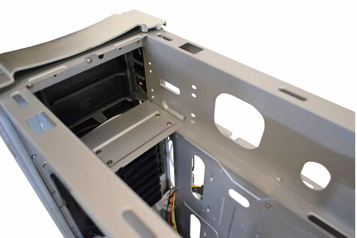
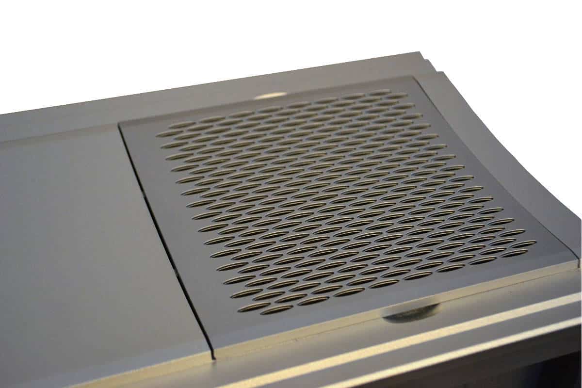
After filling the top with the parts that I need it’s time to replace the top cover that secures itself with two thumb screws in the rear of the case. The top is aluminum and the vent cover is plastic but in this model the difference in color is very unnoticeable except to the average excessive compulsive people of our community.
Placing a drive into the bottom primary drive bay is as easy as lining it up and pressing in firmly. They square hole at the top as two friction tabs that keep the drive stable and the tolerance of the drive placement is so good that the drive is an exact match to the module. This has a down side since if you decide to pull the drive out there is a thick fabric release to pull the drive back out but if you are not the “Incredible Hulk” you may not find this solution very easy. The drive fits so well that it almost melts into place so there will be absolutely no need to worry about the connection losing their grip since I have still not been able to remove the drive by hand as of the writing of this review so, be careful to make sure that you have the drive that you want and it is ready for use or you may find yourself removing the back plate connector to remove the drive.
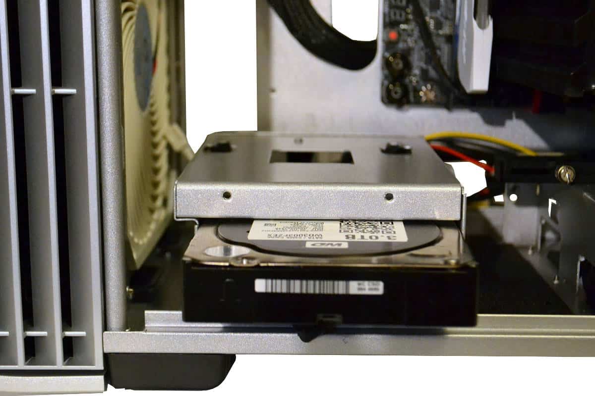
As I have stated over and over in this review the drive does fit flush and tightly in so once it is installed you will have nothing to worry about the tool less design. But removal may not be so tool less, but this can be considered bad or good depending if you are a “glass half full or a glass half empty” type of builder.

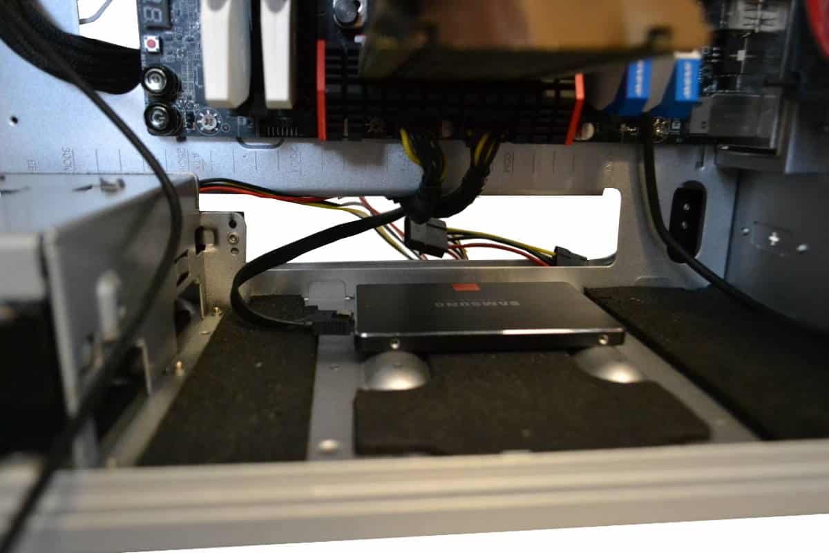
2.5 inch SSD placement will need to be done from the bottom of the case with four screws that are provided if you drive did not include mounting hardware. Here is a colored diagram of the green modular mounting points and the red placement of the SSD mounts. The SSD’s are mounted off the floor slightly to allow for wires to fit comfortably into the bottom of the floor. You will have to give up at least one of the bottom hard drive modules if you plan on using SSD’s. the placement is easy to fit into and the screw to mount the drives are there and you can add as many as 4 SSD’s into the system without using double sided 3M tape of the gods to add others.

The SSD placement is very well thought out and raised from the floor a few millimeters, so you will have ample room for plugging in SATA connections and power cords Molex connections and the look is pretty solid as the mount itself. That said you will have to sacrifice a drive bay that would fit in that same placement above it. It’s simple math in this case. If you need the module or you need the brace then you might want to consider double sided tape to mount an SSD in another hidden spot of which there are plenty of secret out of the way places in the Silverstone Fortress FT04 to mount one anywhere out of sight; behind the motherboard tray or up top near the power supply area.
Personally I do not see a reason that someone would need this unless some was to use a very thin cheap board with no mounting hardware on the back. The CPU cooler brace could be needed if you intended on moving the computer and you may have to drop it down hard for some reason, but for the most part this is a nice thing to have but not really needed in a quality build unless your cooler is not properly mounted to the back of the motherboard or if it’s made of lead.
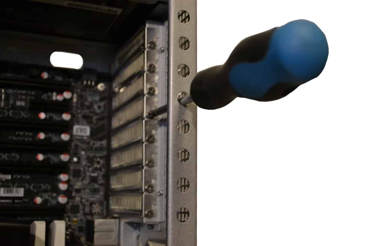
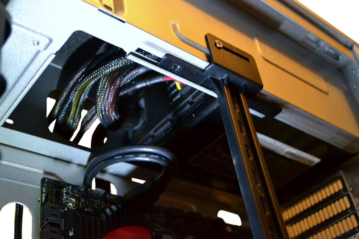
One thing you will need is the graphics card stabilizer. This mounts into a slot at top and then is secured by a screw. The slot allows for many different graphics card placement so it is adjustable as you can notice at the picture below. I have moved it back to the furthest toward the back to give stability support to the graphics card. Since the motherboard is reversed in this case this piece is needed to keep the graphics card from bowing down with gravity and touching or arcing against the CPU cooler. In this build I also used this support to hide my GPU Card power wires as well so it is a great and important little component of the case.
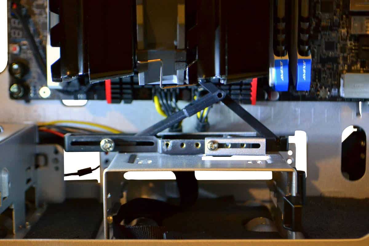
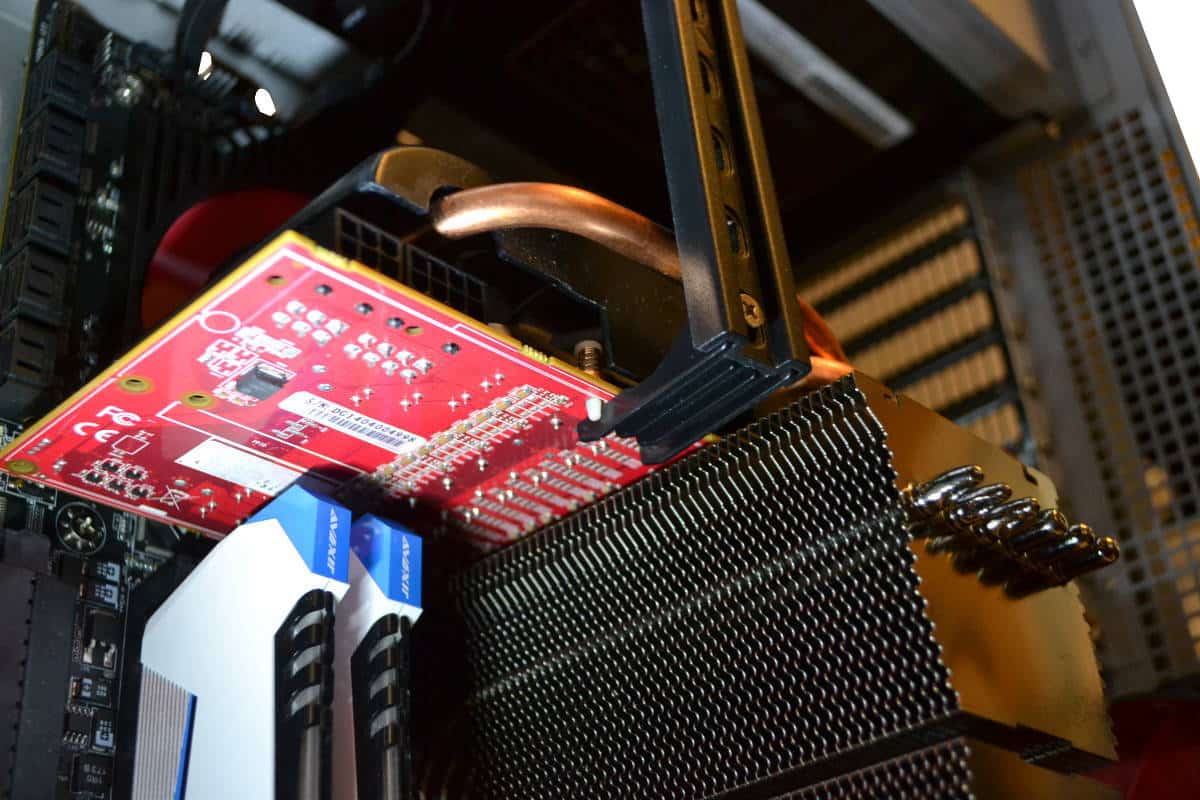
The foot or support that is attached to the support beam slides under the graphics card to hold it away from accidentally touching any metal of the CPU Cooler. This one holds the card about 2 millimeters away from the cooler and fights the law of gravity from letting it come into contact with the metallic cooling element of the CPU cooler.
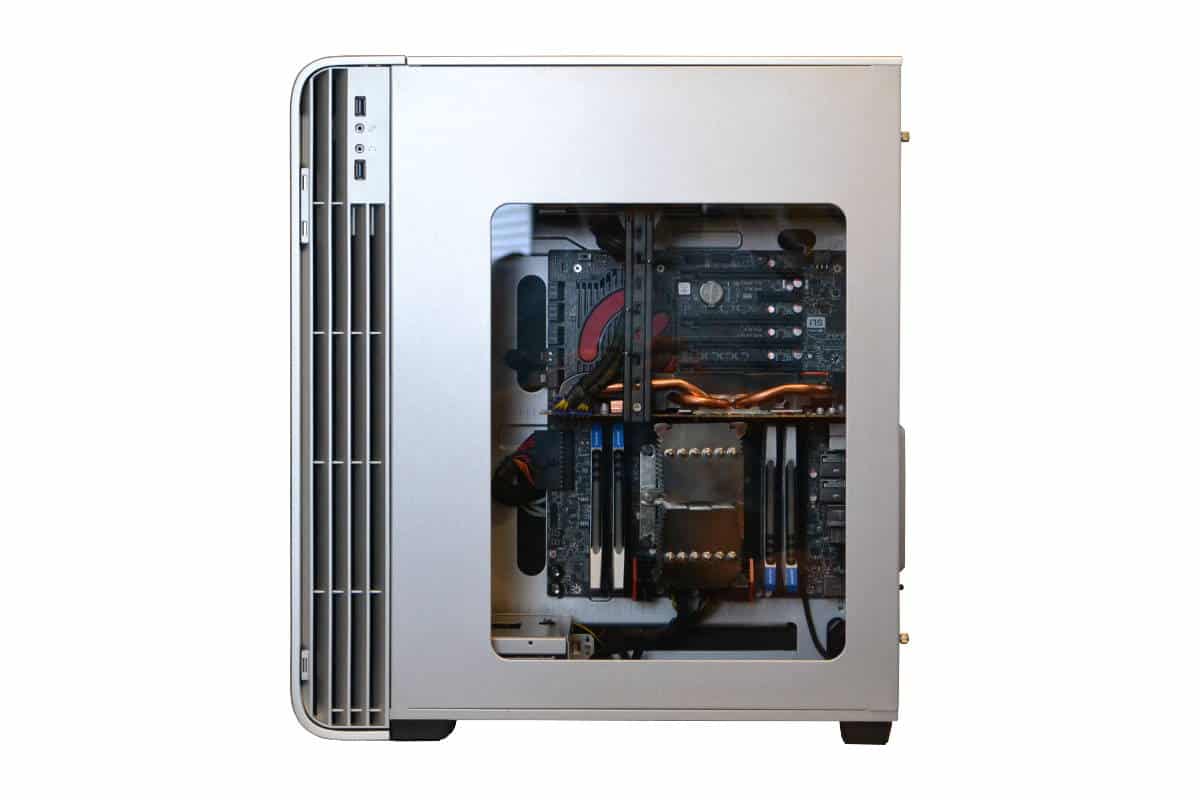
Below shows that even an bad wire management job can still fit behind the motherboard tray. I counted 2.2 cm of space behind the motherboard to the panel anyone can fit the wires behind this motherboard even if you have a non-modular power supply. There are plenty of tie downs and there are never enough wire ties but I was able to close the panel without any problem or resistance from the panel that I closed over it. The panel and the sound dampening material did not hinder the closing of this case even after this terrible wire management example.
This picture of the completely wired build shows the back panel secured and the look of this case with the black and red board looks great. Remember that this EVGA X79 Dark Motherboard is E-ATX and you can see how much more room there is for more motherboard. The look of the large motherboard looks more like the average ATX motherboard installation but its extended
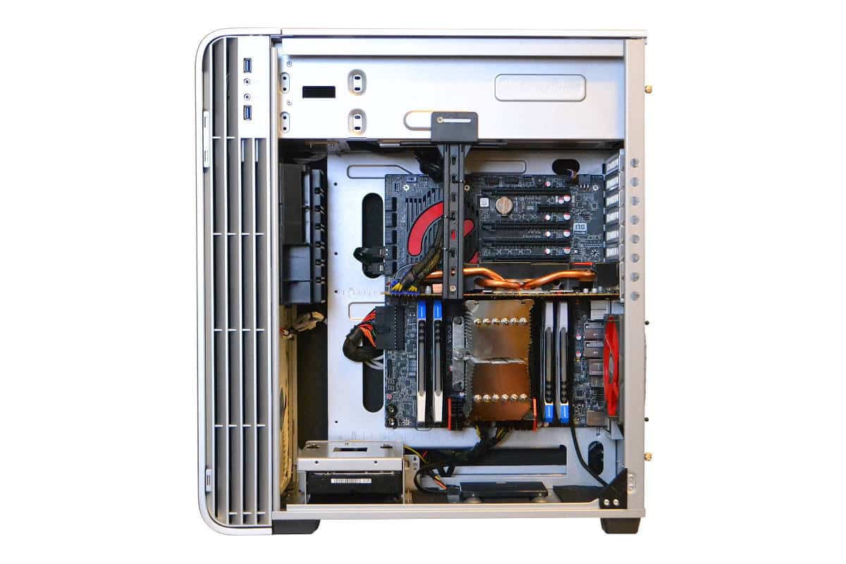
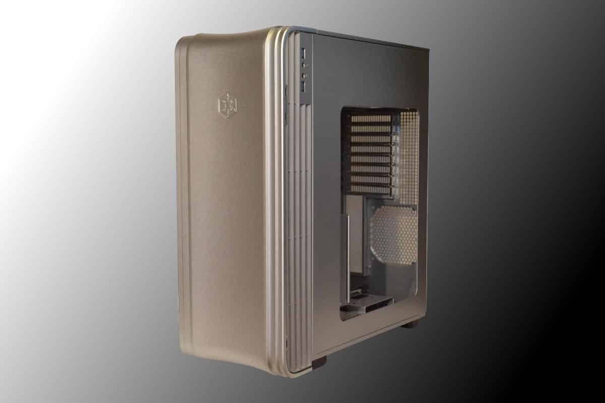
With the door panels completely secured over the entire build of this medium sized Workstation you can see that the case is fully capable of many different application and really a nice looking case.