

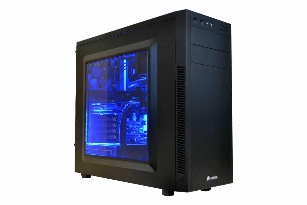
Building into the Corsair Carbide 100R Computer Case
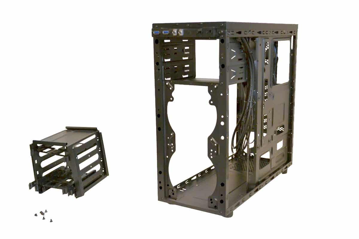
The first thing I like to do before a build is preparation. Prep can be the difference between a good and not so good build. So I started by removing the drive module at the bottom so I could mount the H100i Cooler in the front. The fit is so tight that I had to drop the radiator in at an angle and then I put the fans on the outside and sandwiched the steel from between the fan and the solid radiator. There is 0 tolerance here and I would only use a Corsair h100 for the front since it just fits with no room to spare.
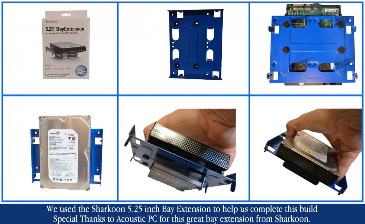
We used the Sharkoon 5.25″ drives extension from our friends at AcousticPC dot Com. The product is hardened steel and fits into one of the 5.25 in. bays and gives you a place for two SSDs and one Mechanical all in one slot. It made up for the drive bay that I removed down under and almost the same storage for less room so it worked out great.
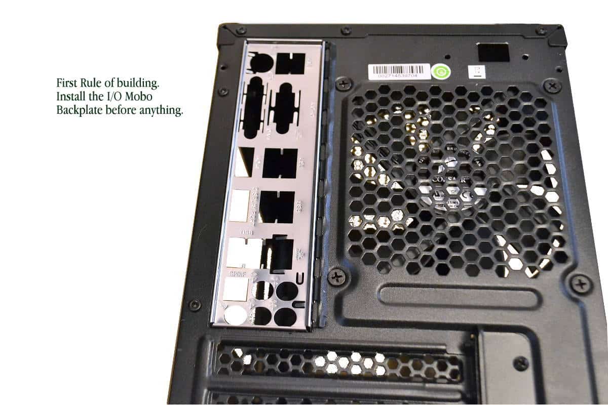
Okay you know the Drill… Time to place that I/O Shield in now before you even think about anything because it’s the best time to do it.
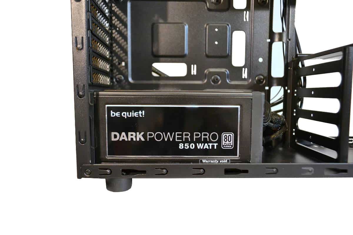
Next we installed the power supply in place and routed the CPU Power Cable through the hole. In this picture you can see there is only Millimeters of clearance. This is the reason that if you put anything up top it should only be fans with rubber mountings because if you just use fan screws you are going to hear every move the fans make.
We mounted this particular power supply fan up because the fan down would not line up with the bottom hole and the heat can get sucked down from the Graphics card and expelled out of the case from the bottom and the exhaust fan.
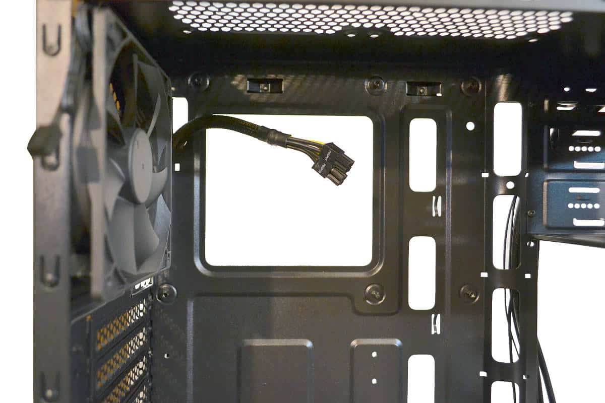
Before you line up the board get your P8 Pin and plug it in before you start to mount the motherboard or you will be taking it back out and doing it again.
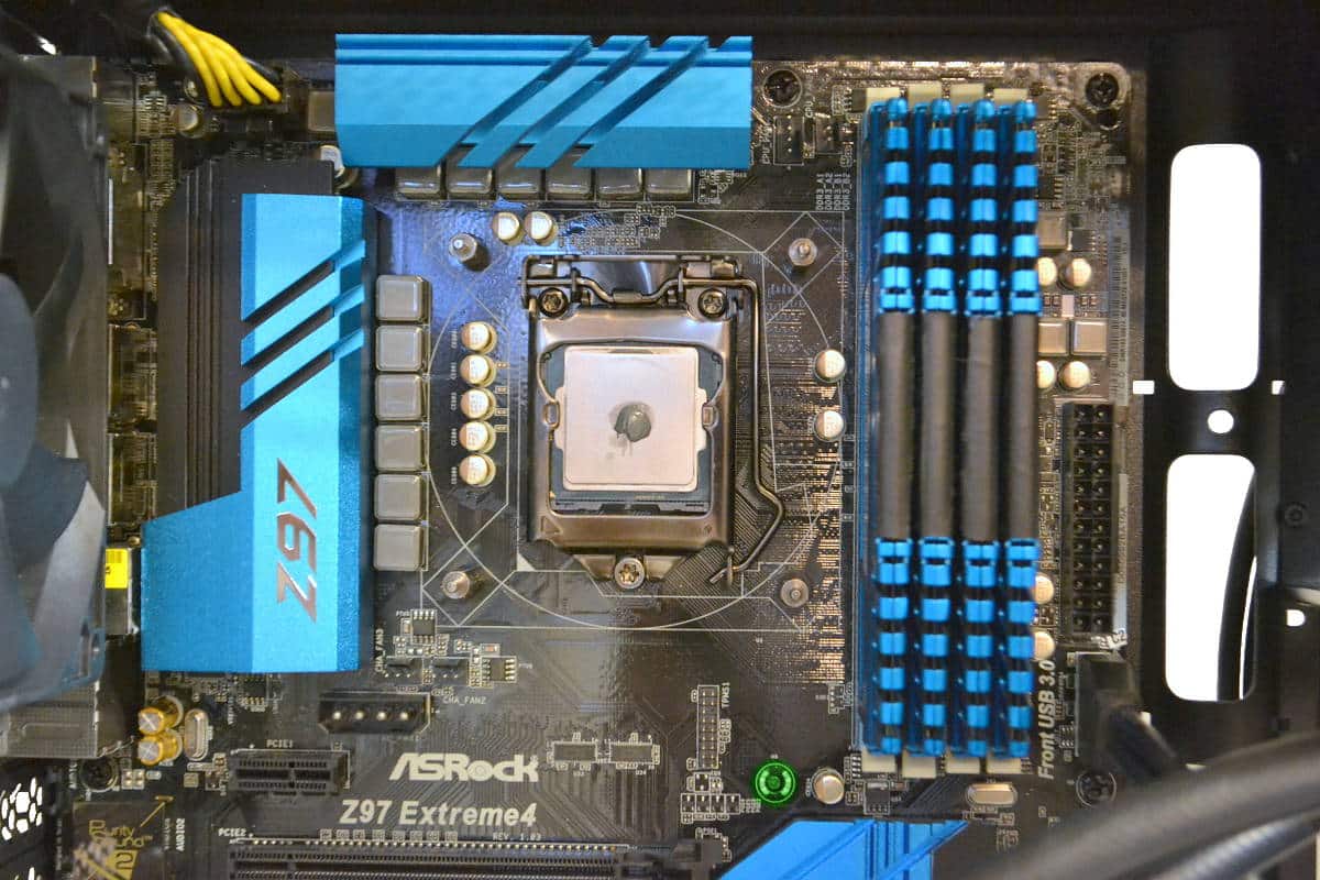
The Picture below is showing the CPU Power or P8 Pin being plugged in even before lining up the board inside. The ATX board fits perfectly but it does not leave much room for working so make sure you pull enough wire out the move it around under the board or cut a new hole at the very top that is 90 degrees off from the built in hole. In addition there is also the half English pea sized Thermal Interface Medium we call TIM or paste. We have to install it for these builds because we reuse the same cooler over and over with the builds to keep down cost of reviewing.
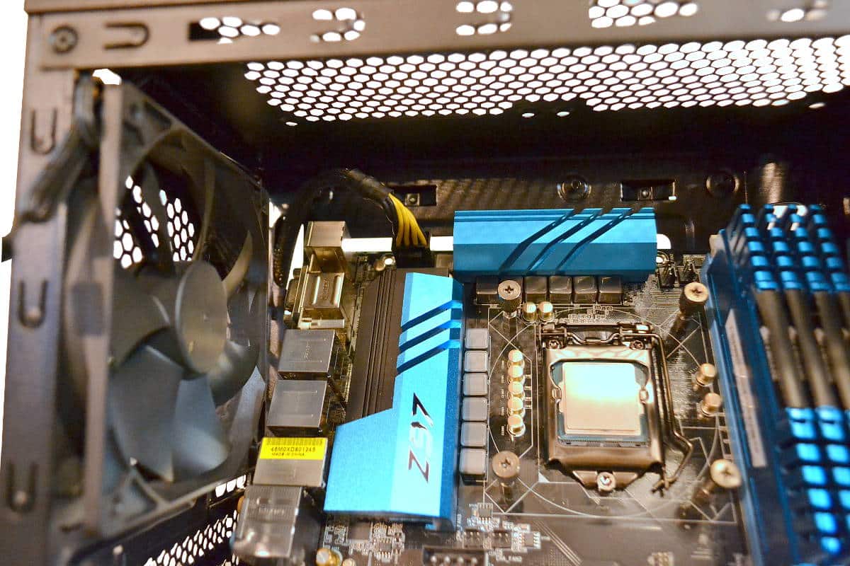
Now that the CPU Power lead was connected then it was time to align the board and screw it down to the standoffs. Remember to check your board for different standoff configurations and after you have that all worked out then just slowly line up your I/O ports to the shield and then work the board slowly until you get the MAP (Motherboard Alignment Pin) tapped in. Now take a look at the clearance on to of the board to the top of the case. That may be a few CM but not much.
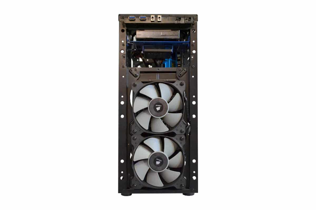
Here is the front of the case after I installed the H100i water cooler into the front of the case. Again everything fits perfectly to the last millimeter so use a Corsair cooler for this one if you are going this route just so you perfect alignment and clearance for the radiator. We used the long screws to mount the front fans through the case to the radiator to hold it all into place and it was amazing how quiet the front is with the front panel on.
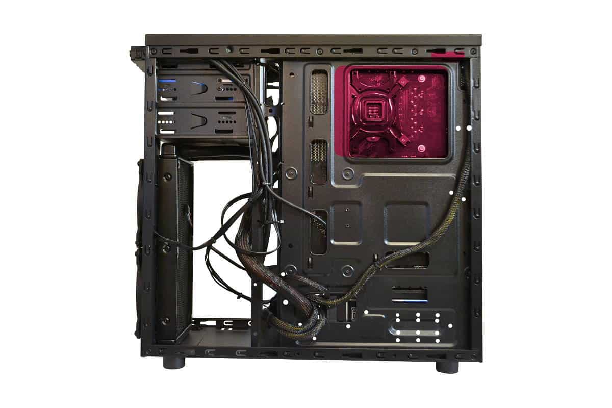
Below is the cutouts and the drill holes that would add for my build if it were my first build. The red indicates the Full ATX Clearance hole extended in red and the above CPU power P8 access hole that will help you with round cable. Corsair uses a ribbon type of cable that makes it easier to use the hole that is already punched out. The white holes are just tie down spots for non modular and modular cables that are used and stored.
Finally noticed that I snaked the Big 24 pin main motherboard cable around the tray instead of using the access holes. It allowed for an easier bend and less problems closing the back panel cover.
Here is the build completed. I did add the extra lighting that I got from Advance Autoparts in my hometown but any auto parts place will do. Also while you are there get a pack of 100 small wire ties so you can do your wire management and make all the mistakes you want. four wire ties are not enough.
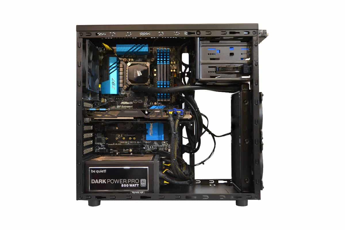
Very last thing to do in this case is to connect the graphics card and finish wire management then close the panels.