

Building in the Prodigy M Micro-ATX Case
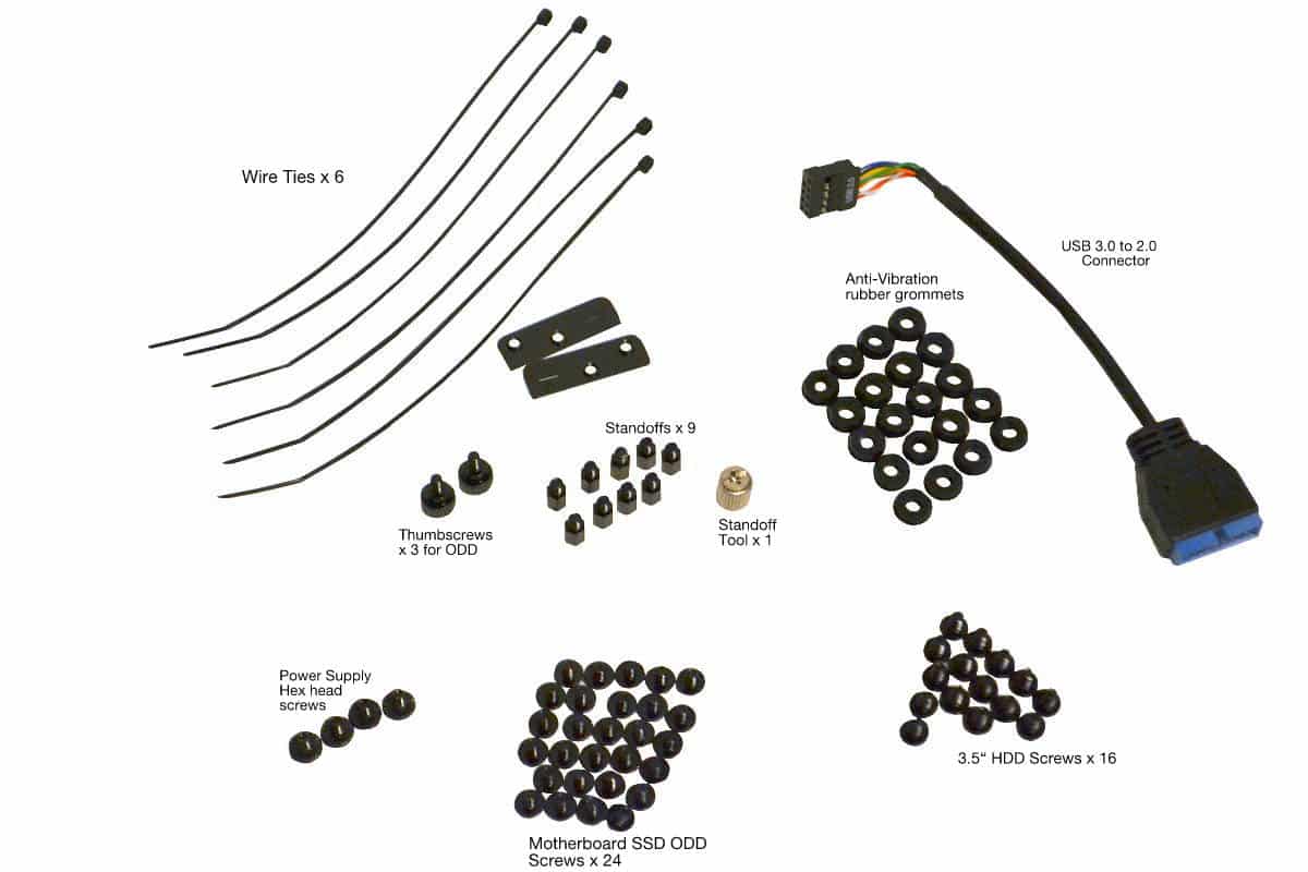
Before we start I will go over the Standard Accessories and Screws that are included. The book lists them like this but BitFenix is still tweaking on the side of the builder so I wanted to show what I got as well. Here is the official manual list:
Accessories:
– ODD Bay Screw Brackets: X 3
– USB 3.0 to 2.0 Adapter
– HDD Anti -Vibration Washers X 4
– Motherboard Standoff grip tool X 1 (For loosening and tightening MB Standoffs)
– Cable Ties X 6
Screws included:
– Standard Screw M3*5mm Round X 24 (For SSD/ODD/MB Tray)
– Motherboard Standoffs X 9 (Black color, MB Tray Mounting)
– Thumbscrews M3: X 2 (For ODD mounting)
– Standard Screw 6*6mm Round x 16 (For 3.5″ HDD)
– Standard Screw 6-32 Hex head: X 4 (For PSU Mounting)
Now here is a picture of what I got with my box:
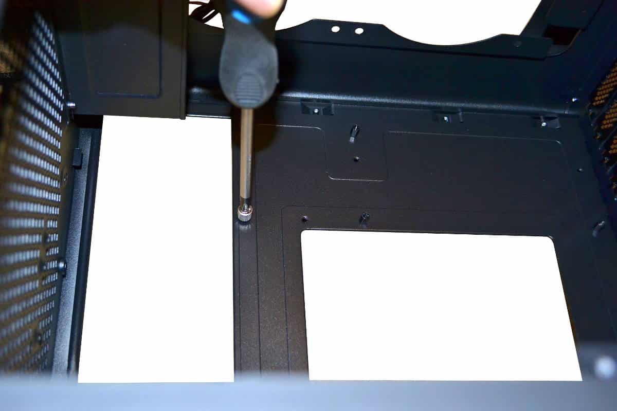
Building a system inside a tight case environment can use all the skills you have as a builder. One thing to remember is to think about every part of the build before you do it. I took about 24 hours to mentally plan out my build so that I could get everything to fit. I wondered if I should mount the radiator at the top or the back. I also wondered about placement of the graphics card and I really wanted to use the primary 16X Lane slot for my graphics card so I wanted to try to do the hardest way possible to show that it could be done. Most of all you want to look at your motherboard to see actually what standoffs you will need and put them in the right placement. Since the motherboard mounts upside down you have to think twice about standoff placement but if you go slow and careful for this process it should not cause any problems. The silver colored part at the end of the screwdriver is actually the standoff tool and you will need it. The holes are tight so use a medium tipped screwdriver for this so you can torque down your standoffs all the way down and not strip out the standoff tool.
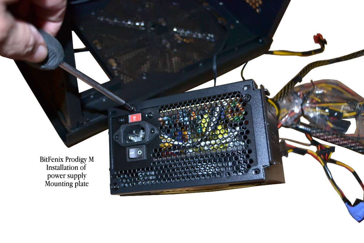
Now remove the power supply mounting frame that is attached at one side by some teeth that fit into slots and then the front is tightened down by a rubber coated thumbscrew. Now is also a good time to mount any drives to the floor of the case or to install any fans that you might need to use for this build. Remember that the power supply will be expelling hot air out of the bottom of the case so make sure that if you are installing fans on the bottom of the case that the air flow is blowing air down out of the case to keep the hot air from the power supply from leeching back into the case build area.
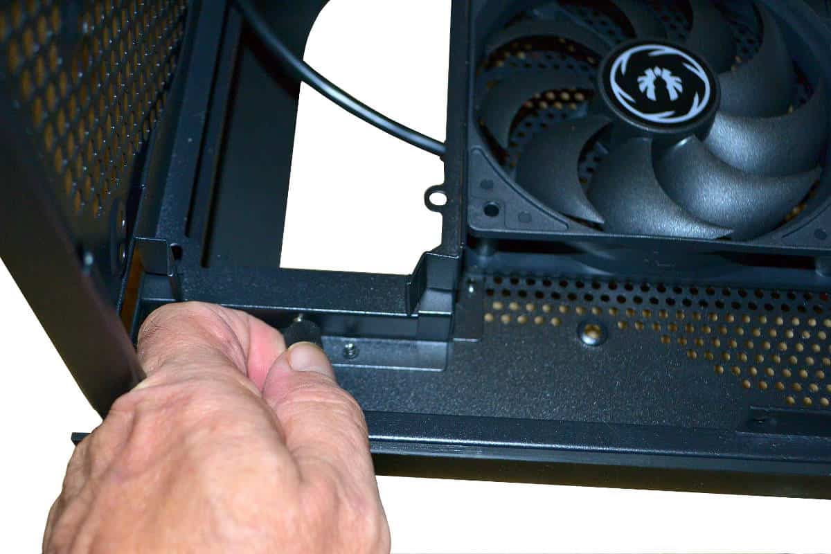
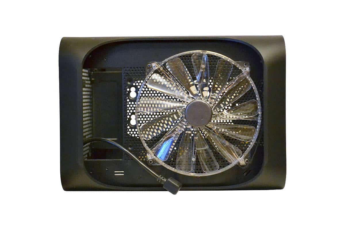
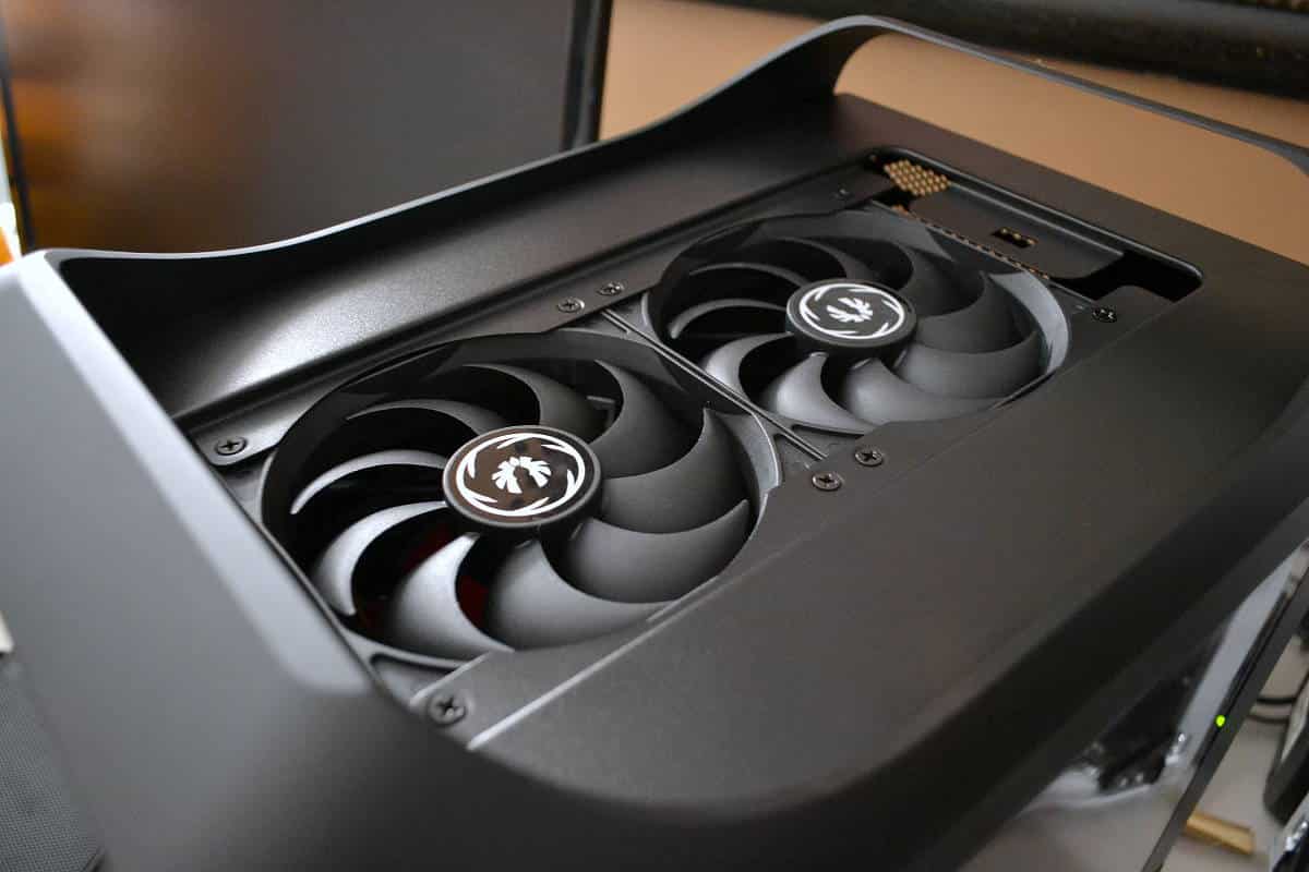
I added a slim exhaust fan that used to fit at the top of one of my other cases. It lights up with 4 x white LED’s and it expels air well but it is the noisiest fan in the build so if you decide you want to use a 200mm or 230mm fan make sure you get one that is as silent as the BitFenix fans and you will have a very quiet system. But this was all I had for this configuration but I should have used some rubber grommets to get the noise level down but overall I wanted to place this fan at the bottom outside the case to give more dramatic lighting from the bottom of the case and it did just that. Another reason for the fan was there was not much room for the push/pull fans of the H 80i CPU cooler so I wanted to keep the air flow going down and out and stronger negative pressure inside the case for more airflow through the back mounted radiator.
After I had the bottom of the case fan where I wanted it and routed the wire through one of the front holes I then turned my attention back to the power supply mounting frame. This frame will allow for the power supply to be mounted with the fan forward or the fan back but I wanted to created as much negative air pressure for the H-80i to breath more efficiently so I placed my power supply fan towards the back of the build to suck air from the motherboard area and out of the bottom of the case. The bottom fan exhausts this air also creating positive pressure under the build to allow for maximum heat dissipation.
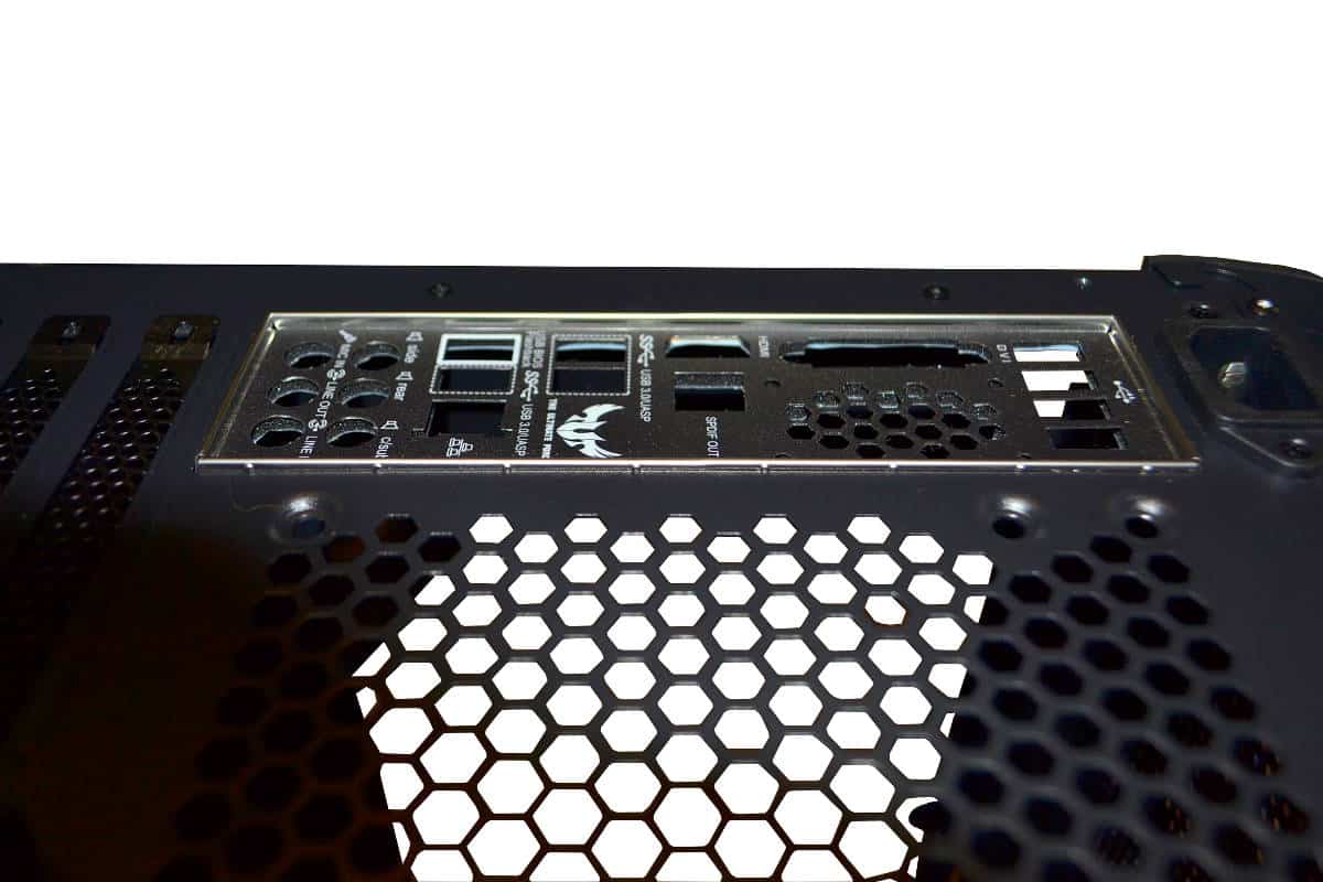
Always remember to install the back-plate I/O shield into the back before getting too far into your build. One hates to take things apart especially after working in a confined space because you forgot to install the I/O shield and believe me this happens to the best of builders so make sure you get it in as fast as possible and in the right orientation for the motherboard to properly fit into the ports.
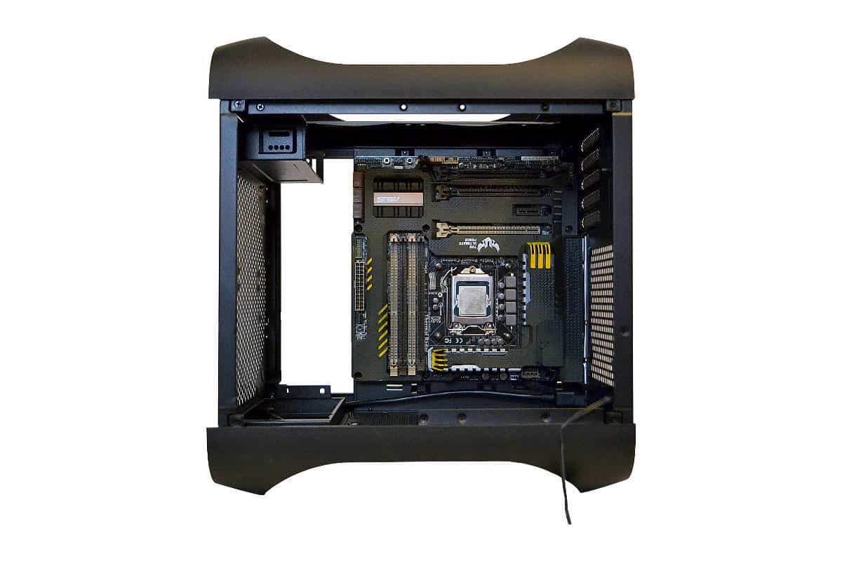
I broke the cardinal rule of mounting the motherboard before mounting the power supply because of the confined area of such a small case to work in, but also to show how the motherboard looks in the case. I also removed all the fans that come installed in the case for later install at the top of the build for greater intake of fresh air from the top. If you choose to mount the motherboard before you mount the power supply into place make sure that you either use an 8 pin extension CPU power cord before mounting or run the wire behind the motherboard into the case and affix the wire before mounting the motherboard to the standoffs. If you do not do this you can remove the rear A/C extension cord from its mount to get to the plug the replace the extension cord back into the case frame. This is probably one of the most problematic parts of the building process with the Prodigy M.
Here is the power supply installed in the fan back position but with the black edition of this case you can mount the fan forward because of the meshed front cover. The power supply frame was easy to reinstall back into the case with the power supply mounted and I just routed all the wires for the time being to the back of the case for the wire management portion of the build later on.

Next part was to attach the CPU cooling block onto the CPU. This was easy since there is plenty of room to get to the CPU bracket from the back of the case. The hole for accessing the CPU from the back is very large and made affixing the CPU block into place without much problems. Getting the extra long hoses to route into the case and place the radiator at the back was the tough part. It took me several tries to get the first screw into the radiator mounting hole but once I got the top back screw in the rest were easy. I would suggest to anyone using the Push/Pull H 80 to make sure that you mount one of the fans outside the case for full potential of this cooling design. It will even be easier to get the radiator mounted but make sure that you mount the back fan in before installing the radiator in the case. It’s very important that you do as much as you possibly can before you install the radiator into place and installing that back fan is one thing you really want to have done before you mount the radiator.
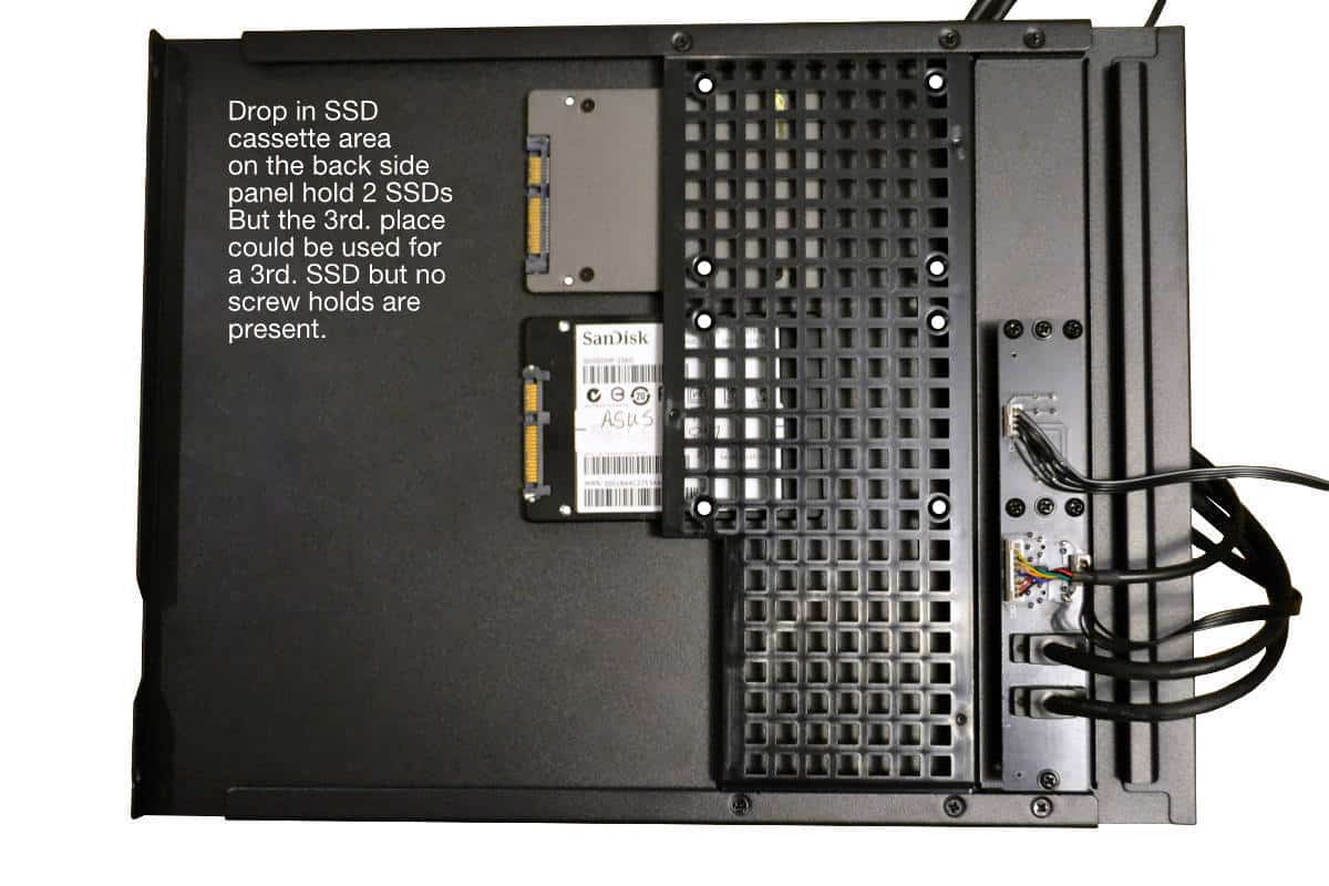
I made sure to not connect any of the back case panel control wires before I got the SSD’s installed. The basically drop in and can fall to the bottom and away from the mounting holes so hold the SSD and slide it into place having your first mounting screw ready and tighten it down enough to move it but also enough to keep the SSD close to the mounting holes. those screws are short and this is the best way to mount them. One at a time in the fashion that I described.
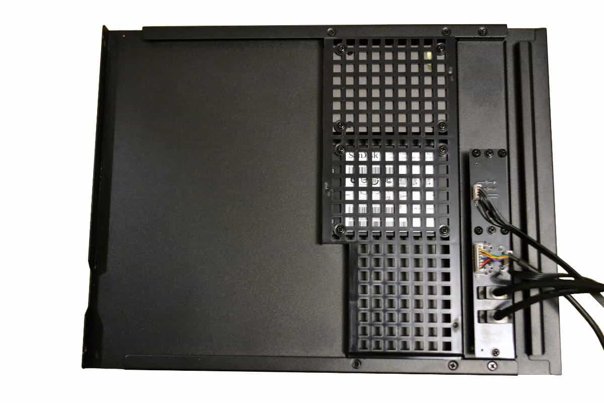
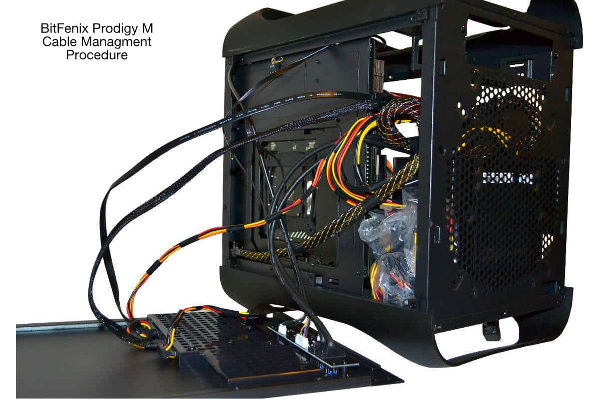
After the SSD’s are installed into the cassette you can start to wire things into the back panel of the case. Wire management is tough so be resourceful with how you route your wires and only use what you need an nothing more.
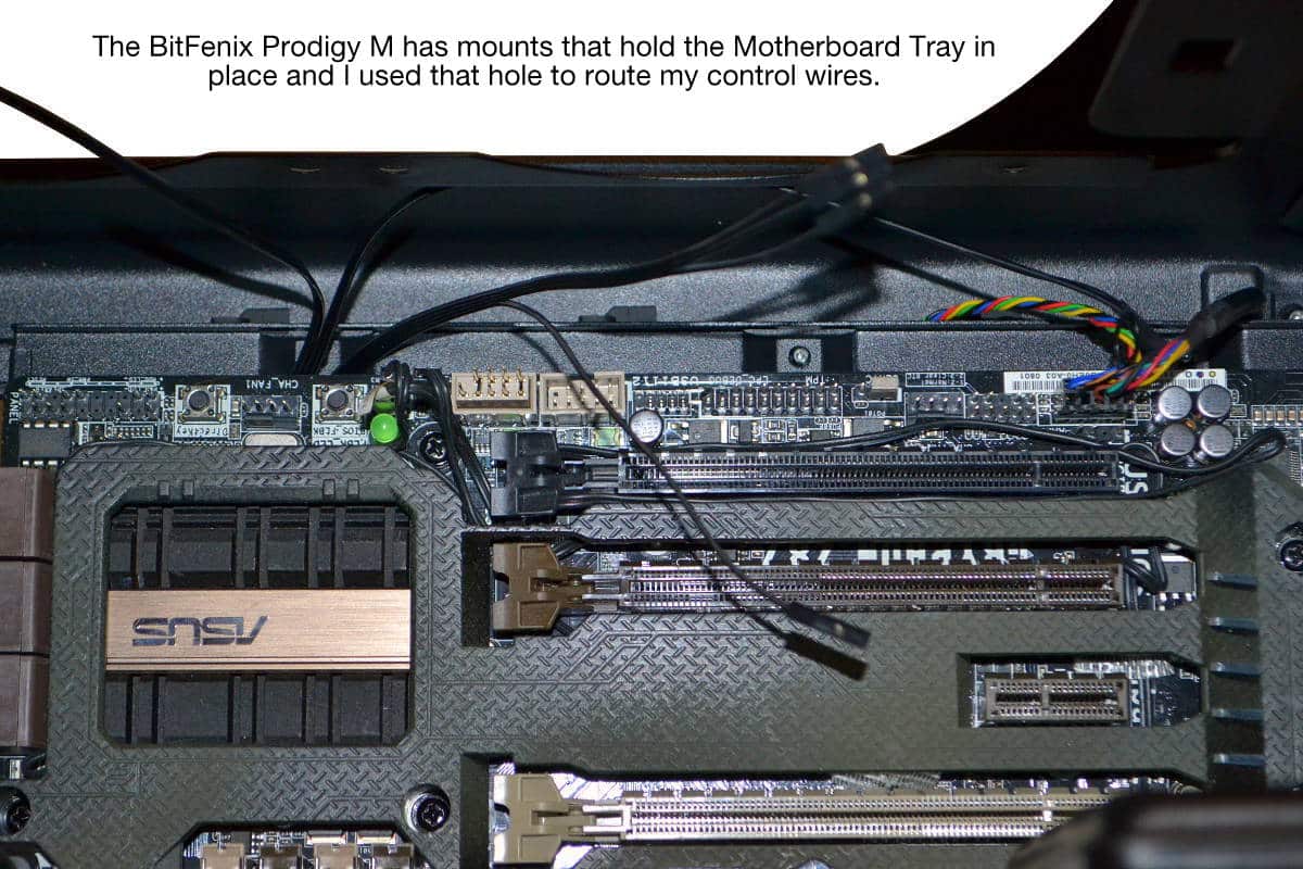
One thing that I discovered about this case is the motherboard tray is mounted out from the back of the case with some extended cutouts. I used one of these cutouts to route all my control wires through and then hooked them up this way. It was cleaner for the overall build and made it easier to get them all in one convenient place.
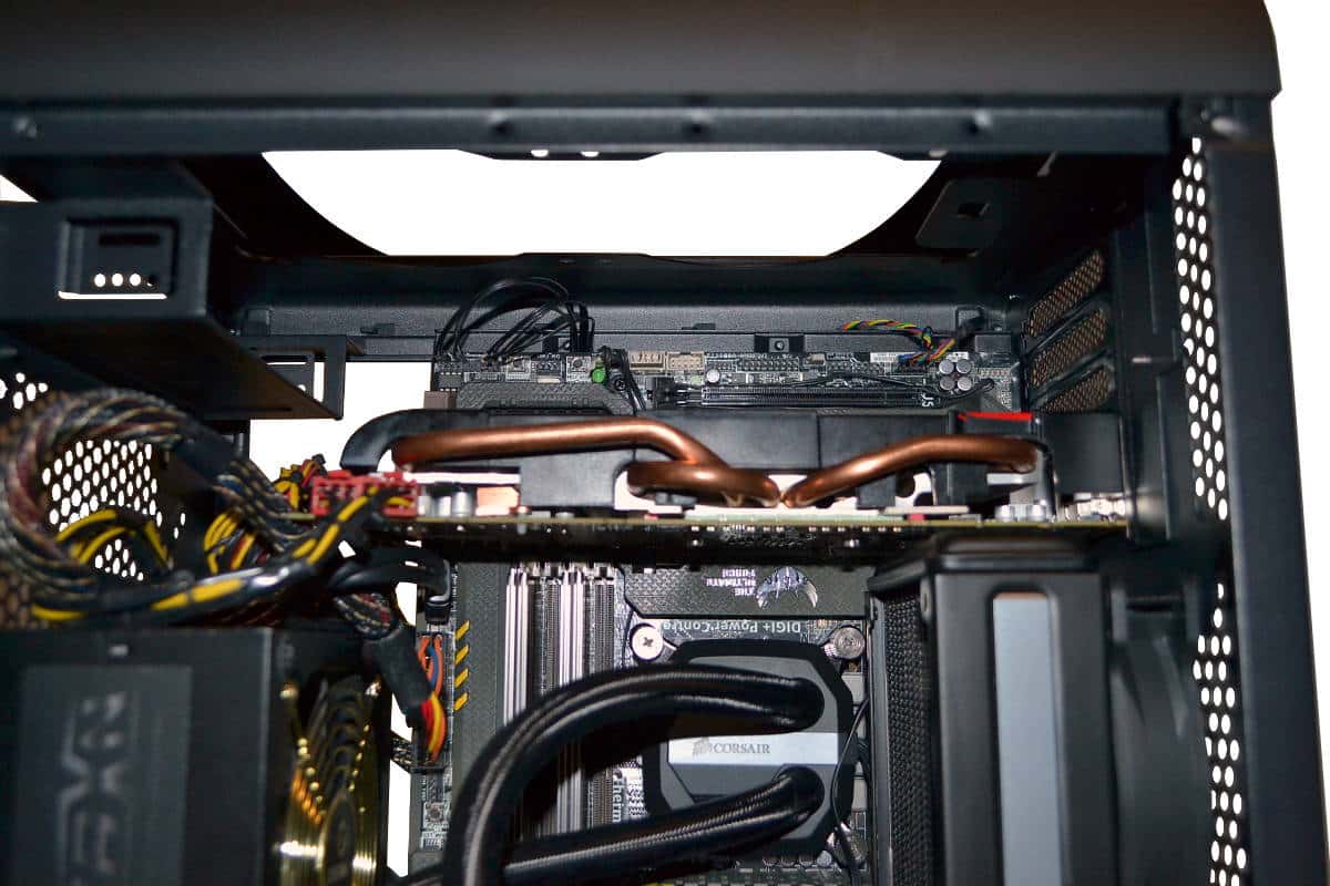
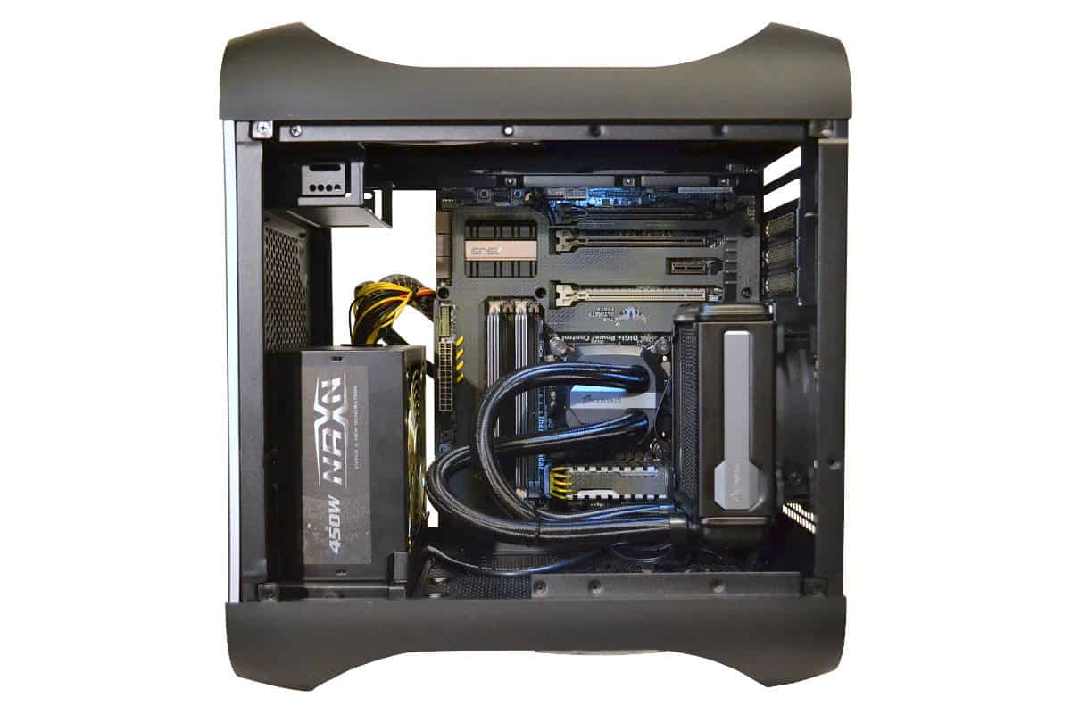
At this point it was time to mount my graphics card into place. The All-In-One PCI bracket support in the back will not let you miss-align the cards by even a millimeter. They have to be exactly in place in order for the support to close properly. This picture was taken at an angle and there is about 2mm of space between the graphics card and the radiator so I placed a small hard cardboard cutout that cut out of a box and made it to fit between the radiator and the graphics card for no possibilities of sparks since the gap is very close. One could affix a non conductive material onto the bottom of the radiator before installation too to keep the graphics card absolutely safe. I probably went overboard on this but I am very careful even with my older cards like this AMD 6970 graphics card.
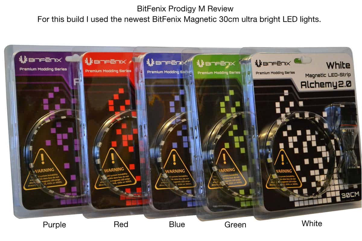
The last part was to hook up the SATA wires, control wires and the power connections to the drives and to mount the rest of the wires in the little cubby hole at the bottom front of the case. I used one of the plastic bags to put my excess wiring into for safety and then I mounted the new magnetically mounted LED kits that I got from BitFenix. These new lights have a super strong grip on the metal chassis and eve works around corners. I daisy chained both the white light on top for brighter overall lighting and the red in the back for accent lighting to give that red glow to it and red and white light mixes well but you could use any type of colors you would like. the lights come with everything you will need to install and daisy chain enough lights to make this build look nuclear and the two 30mm strands that I used had more than enough lighting with the newer type of LED’s that BitFenix is now using with these kits.

Over all I was very happy with the way the build turned out and I installed my free edition of Windows 10 on this build and I think I am going to keep this one for a while. I really like the case a lot and it can be difficult to work a build into such a tight space but it is worth it in the end. This picture was taken in the day time with a flash and the lights are still brightly lit inside the case so that will tell you that these new magnetically mounted LED lights really are nice to work with and to get your lighting just right without dealing with the glue coming off if you need to re-position the lighting like I did.
The new magnetically mounted LED lights look great and were easy to daisy chain and with long wires for Molex power hook up. The variety of lighting they have is great but there is not any black light versions of LED strips yet but I looked on Google and the only true UV lighting I could find was the old cold cathode tube lights, so if you want to go with UV you might want to consider going old school for that effect.