

Inside the Prodigy M Micro-ATX Case
While the inner part of the Prodigy M case has been completely retooled there are things that have stayed the same throughout this total refit of the classic Prodigy cube case. The front for example has not been changed at all. In fact my black case still has the mesh front but the colored Prodigy do not have mesh but have a solid colored cover but under the cover has not changed at all. BitFenix did not see the need of changing something as unimportant as the front frame panel and kept it exactly the same as the Prodigy of before. It has screw holes for fan placement but forget it. There is only a few millimeters of space between the panel and the body of the power supply so you have the option of putting the fan forward or fan in the back of for power supply fitting but forget using any fans in the front of this case. There are no fans that will fit into these holes unless you plan on fitting a fan on the outer part for an extreme modification. This is a left over from the previous version. The top 5.25 Drive bay can be used for fan controllers, square reservoir or even a Optical disk drive but if you are using this case for an extreme dual video card machine you can take out the fitting for the ODD drive for more space and leave this part blank.

The rear motherboard tray is all new with the reverse motherboard configuration and a very large access hole for the CPU mount. The standoffs are not pre-installed and you will need to use the included standoff tool that we will discuss on the next page. As you can see the accessories are mounted on the inside part of the front mounted drive bay rack. Also if you want to see a really neat use of this tray it can be fitted on the back side as well but there is no room for it with the motherboard tray in this position. This was an engineering idea that probably did not make the cut but if some very intuitive Modder needs this mount for an extreme modification they will have the screws holes already there for mounting it if you can think of a way to make it work out. I would not doubt that these will be used for something that I have no idea for now but Modder’s never cease to amaze me with the ideas and ingenuity they use to do the near impossible with these cases, no matter what case we are thinking of.
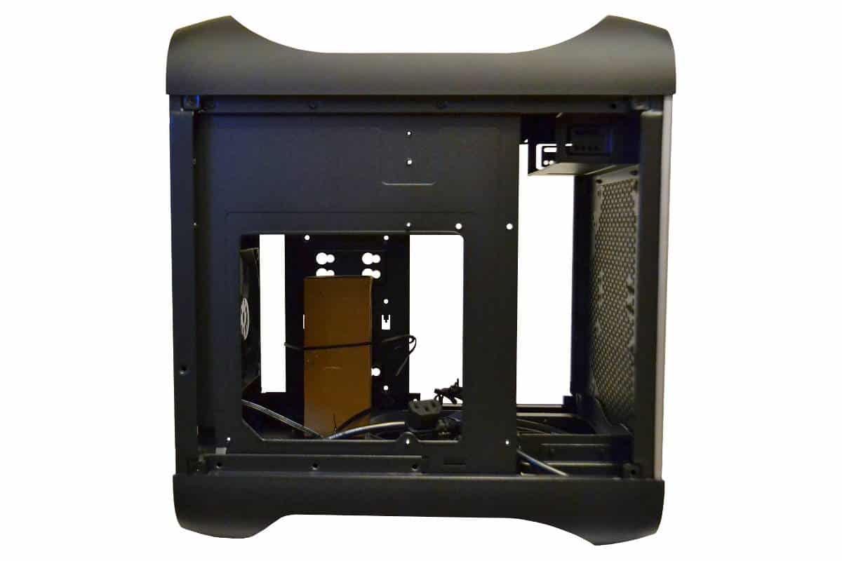
The picture here includes the drive rack installed as it comes when you receive the case. The drive bay rack is removable and I removed it for my build but it’s there if you need lots of drives or you want to make it to hold something entirely different but it’s there if you need it and it’s removable if you don’t need it. I didn’t need it. There are plenty of other placements for both mechanical and SSD drives in other places and I like a clean clear view of the build with lots of lighting so I elected not to use this drive rack. The fan on the bottom is a 120mm exhaust fan and the back exhaust fan is also the 120mm variety and plain black for looks and cost cutting but I have to say that these fans are whisper quiet so don’t throw them out unless you want the Lighted fans. These are really good fans and make no noise at all that I could tell.
A closer view of the included drive rack shows the front mounting for 3 SSD or 2.5 Mechanical laptop drives. The top and bottom only require two screws to fasten them down using the hook in mount for one side and the center drive needs all four screws to mount it into place.
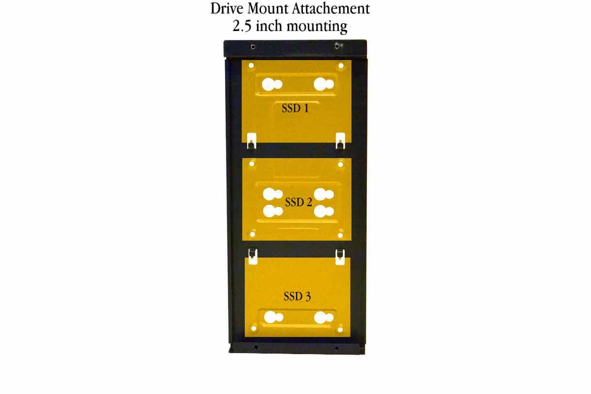
The back of the drive mounting rack is reserved only for 3.5 in Mechanical drives. BitFenix instructs to use either side independently and not use both sides but for Modder’s nothing is impossible and I can’t wait to see what some people will do with this rack as it could be used for many different uses with a custom loop users. This rack was probably pretty useful for solid
side panel installation but for windowed version it’s really not needed unless you are going to fill this case with lots of hard drives. In that case you will have plenty of placement options for an extra 3 SSDs or 2 Mechanical 3.5 inch hard drives.

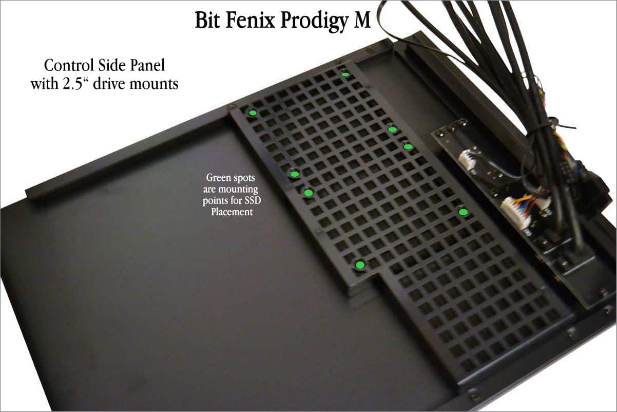
One of the most unique features of the Prodigy M is the rear panel SSD drive cassette tray. There are actually three slot but only two have mounts for the SSD’s to be fastened in, but that last small cassette opening is there and could be used. I dropped a solid state drive into the last slot and it fit perfectly into that bottom slot but it did not have a way to fasten them down but where there is a will there is a way with our modding community so let be known that this can be used if you can make a way to fasten the drive into the last slot. The green dots are the fastening holes for the SSD drives and they fit perfectly but it does take a little ingenuity to fasten them down. I found that the best way is to get a screw ready in the front top hole and then slide the SSD into place and secure it with just one screw then fasten the rest down.
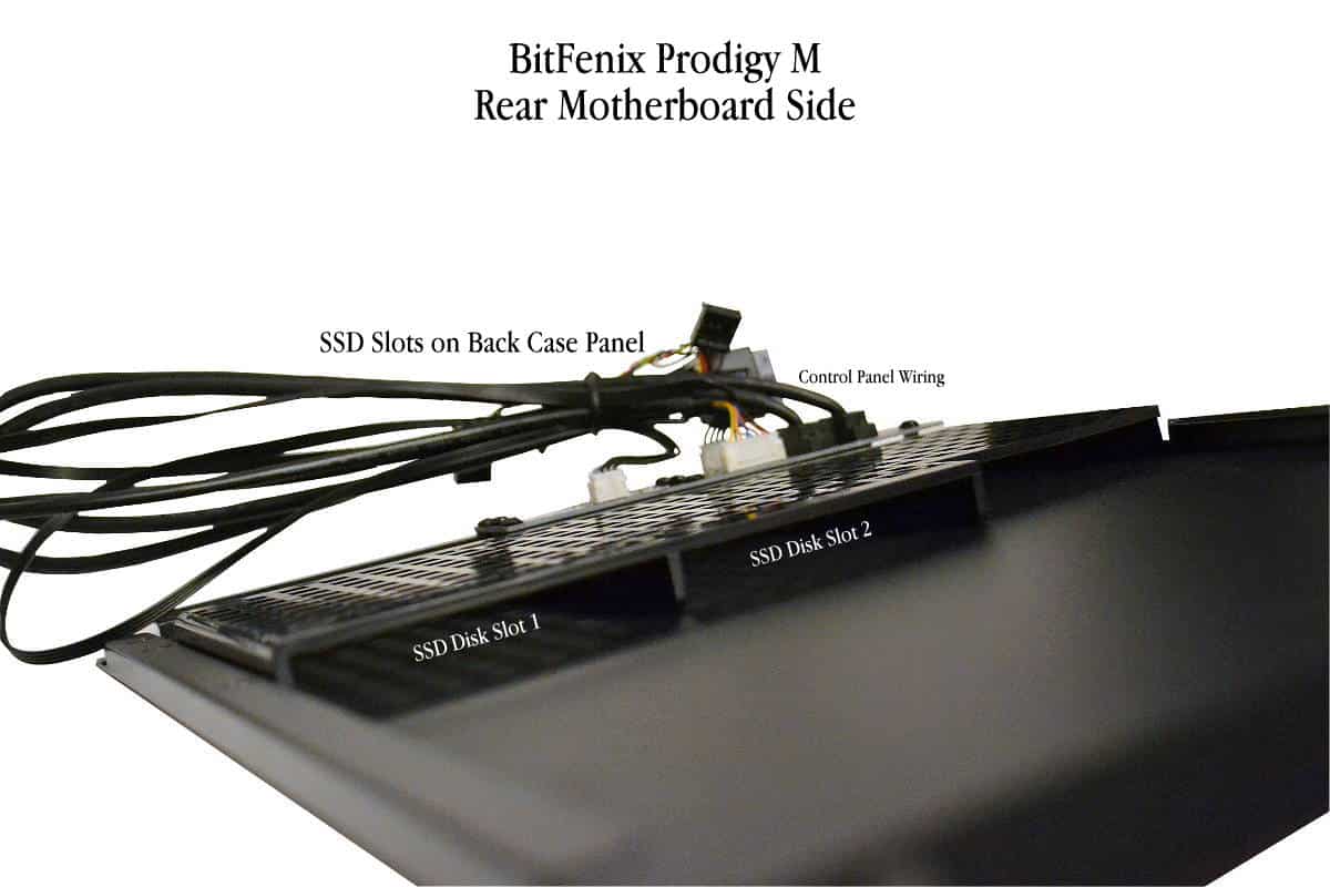
Looking at another angle at the drive cassette tray the reader can see that the cassette is very wide and that third cassette area could be used for lots of different applications like adding a third drive with some double sided tape maybe. Another thing that I would like to mention is the generous length of wires that come on the control Module. This can allow a builder to remove the back cover and not have to unplug everything to get to something in the back. On the other hand the room behind the motherboard is almost completely taken over by the cassette rack so wire management room behind the motherboard is at an absolute premium so what I mean by that is it is very tight behind the motherboard so keep as many wires from the top of the cassette area as you can. One trick you might consider is to route the control wires along the top part of the case away from the panel to make it easier to affix the back panel on.
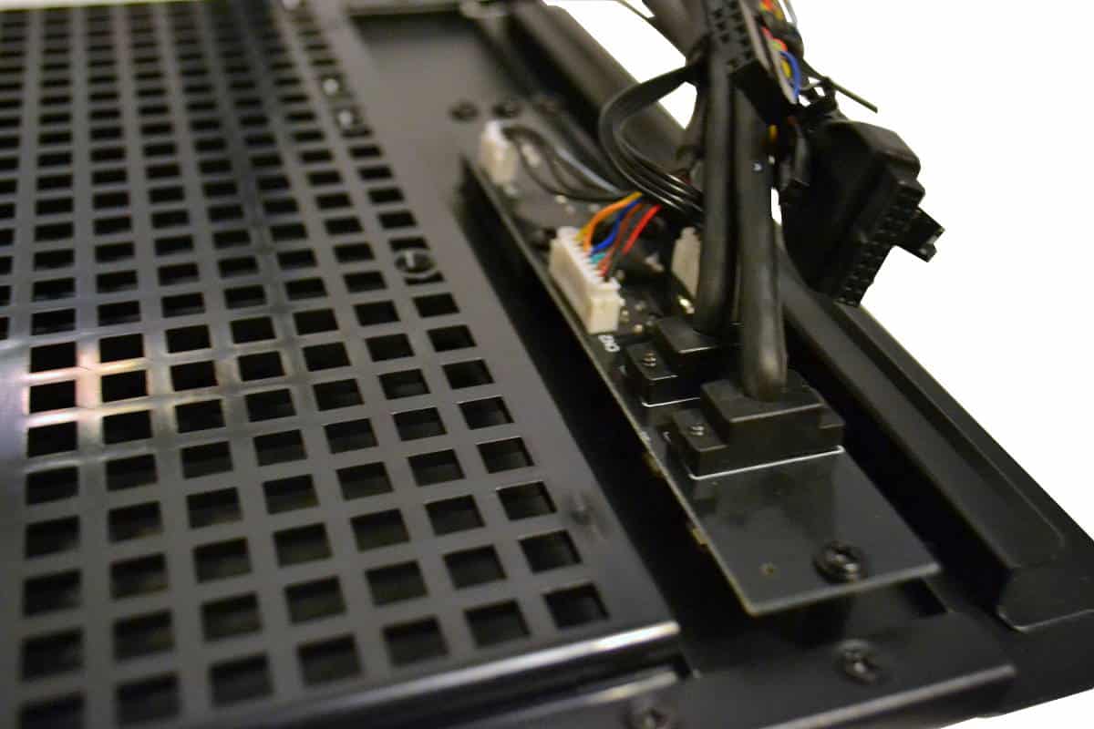
Here is a closer look at the back of the control panel that uses plugs like a BMW lighting and control circuit. The third cassette would be great to use as a wire loom if you could cut a few squares out of the third cassette but don’t cut too much. the cassette tray depends on both sides for proper mounting and cutting straight across would cause more problems than help for wire management. But I love the SSD Mounting on the back of the case panel and I did use these cassettes for my build but let me say again. There is not much space at all for wire management behind the motherboard tray, so think real hard about how you want to route the wires in the back of the case for the best fit.
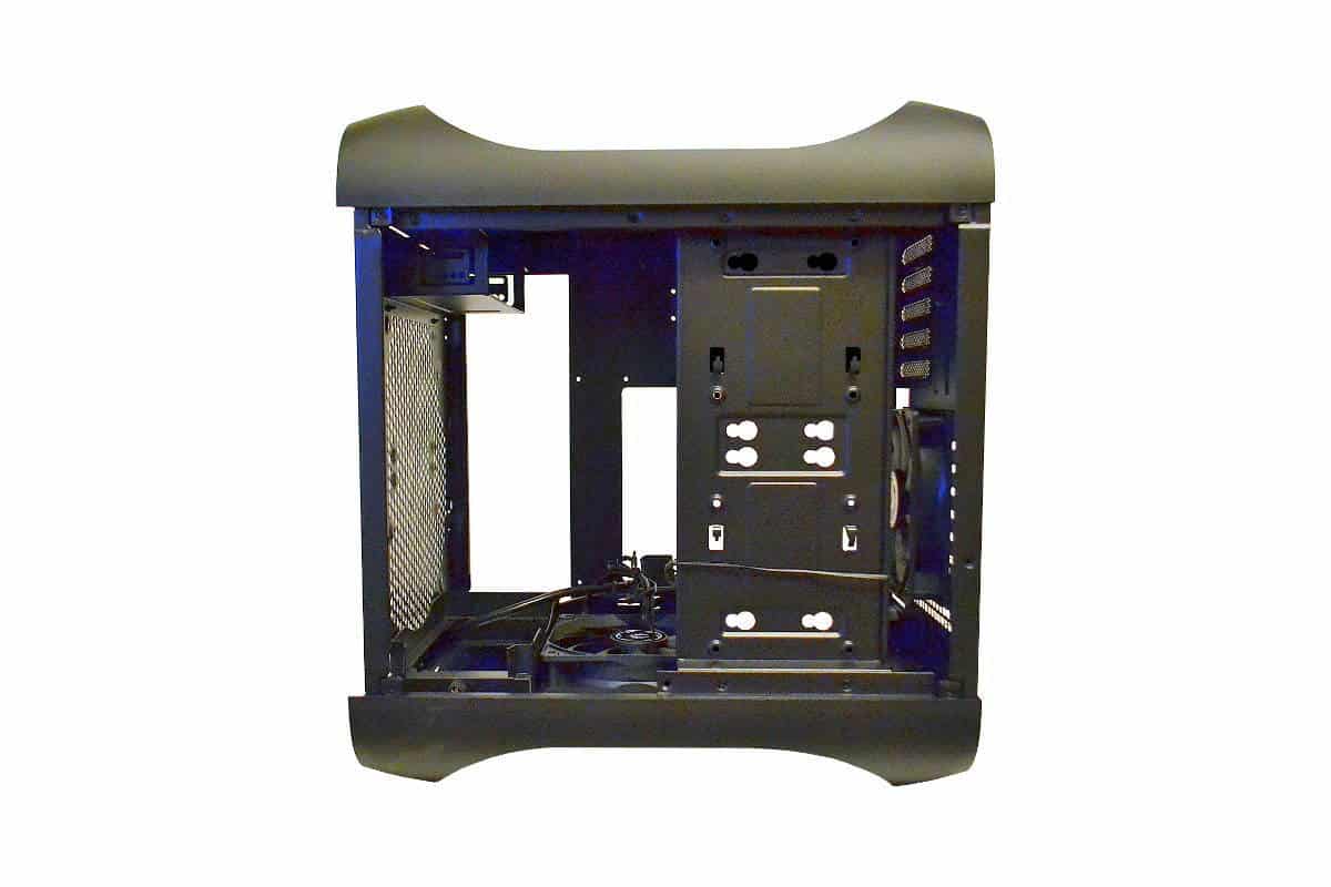
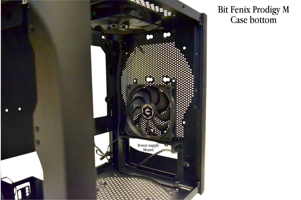
In this picture I turned the case on its front face down so the bottom would be easier to photograph and to show the way that the bottom panel is almost like a common front panel. The 120mm whisper quiet fan comes mounted as you see here for exhaust out the bottom of the case but most important is the removable power supply mount at the bottom front of the case. This is why you cannot use a fan in the front. The placement of the power supply is too close to the front panel to allow for fan placement with this new design.
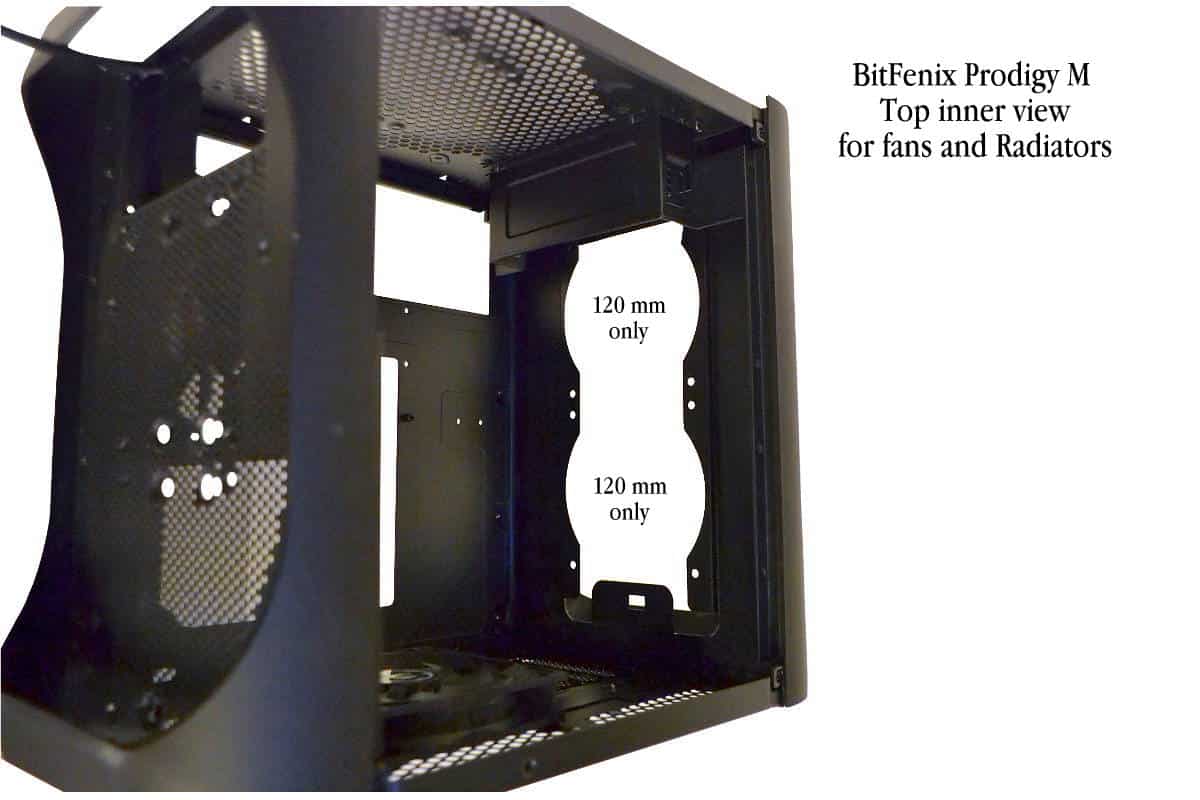
Now with the case laying on its back we can see the top from the inside of the case. There is plenty of intake room for a 120 water radiator or just two lighted or unlighted 120mm fans only. The top of case shows the mount for the 5.25 inch drive bay. It is short this way to allow for that second graphics card to be installed but BitFenix does recommend that you install even one graphics card to be mounted in the bottom PCIe slot but for better cooling of the graphics card, but most of those are only 8x lanes on the bottom, but mostly the reason they recommend that placement is a way to keep the graphics card away from a rear mounted water radiator set up. I used the primary slot for my graphics card placement and used the Corsair H80i into the rear exhaust and just for safety I placed a medium sized piece of cardboard between the top of the radiator and the graphics card, but I was being extra careful so that said the barrier is something you might consider if you are using a rear mounted cooling system but I would suggest using an All in One 120x120mm or 120x240mm Radiator mounted on the top if I had it to do all over again.
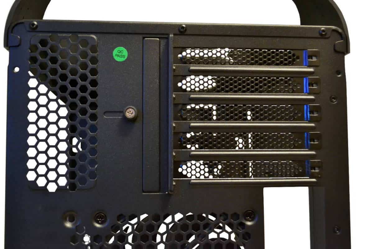
I did say on the previous page that we would get more in depth on the PCI All In One slot mechanism. Here is a close in shot of the PCI top mounts with the mount more visible. The rectangular block protrusion fits perfectly into place with no room for imperfect placement. The card will have to be perfectly arranged correctly for this mechanism to close correctly. The rubber coated thumb screw is only to untighten the protrusion from its slot and to slide it back for adding cards. Once all the cards are in place then slide the protrusion back forward towards the card and make sure all the cards are lined up just right then tighten the screw to get the protrusion into the slot so that you have uniformly tight fit for all cards being used. This process leaves no room for error. If one of your cards are misaligned in any way the protrusion will not fit into the slot and will not engage. This is a Fail Safe way to hold the cards in place and beats getting inside to try to line up thumbscrews into the hole as with other cases. This is a great design and really works well.
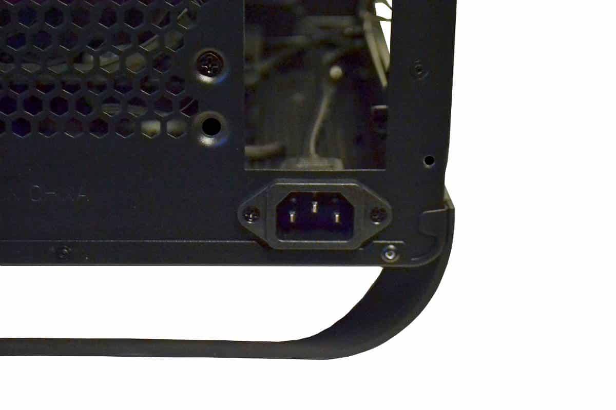
Lastly there is the extension cord mounted at the back of the case wall. I did have to remove this from the mounting point once to get my 8 pin CPU power cord plugged in but it’s just two screws and I didn’t have to totally remove it but just take it back from the outer part of the case to affix my 8 pin cable that I should have installed before I affixed the motherboard to the standoffs so that was my fault and not the fault of BitFenix.